Sign In
Upload
Manuals
Brands
Varex Imaging Manuals
Gas Detectors
PaxScan 2020XV
Varex Imaging PaxScan 2020XV Manuals
Manuals and User Guides for Varex Imaging PaxScan 2020XV. We have
1
Varex Imaging PaxScan 2020XV manual available for free PDF download: User Manual
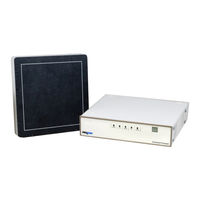
Varex Imaging PaxScan 2020XV User Manual (106 pages)
X-ray Detectors
Brand:
Varex Imaging
| Category:
Gas Detectors
| Size: 3 MB
Table of Contents
Table of Contents
9
1 Scope
17
2 Contraindication
17
3 Intended Use
17
4 Audience
17
5 Abbreviations
18
Table 1 Abbreviations
18
6 Definition of Symbols
19
Table 2 Definition of Symbols
19
7 Standards and Regulations
21
Table 3 Standards and Regulations
21
8 Description of the Detector and Command Processor
22
Figure 1 Customer System
22
Table 4 Command Processor Component Boards
23
Shipment Contents
24
Supporting Files
24
Accessories
25
Table 5 Accessories
25
Detector Surfaces and Features
27
Figure 2 Detector Surfaces and Features
27
Table 6 Detector Surfaces and Features
27
Cables
28
Figure 3 Cable Connections for the Detector and Command Processor
28
Table 7 Cable Names and Descriptions
28
Connecting the Cables
29
Detector Dimensions
30
Figure 4 2020X/2020XV Detector Dimensions (Measured in Inches and MM)
30
Figure 5 2020X/2020XV Detector Dimensions (Measured in Inches and MM)
31
Figure 6 2121XV Detector Dimensions (Measured in Inches and MM)
31
Figure 7 2121XV Detector Dimensions (Measured in Inches and MM)
32
Detector Specifications
33
Table 8 X-Ray Detector Specifications
33
2020X/2020XV Alternative Power Supply Requirements
35
Input Voltage Range
35
Table 9 Environmental Considerations
35
Input Current
36
Noise Specifications
36
Environmental Considerations
35
2121XV Alternative Power Supply Requirements
36
Input Voltage Range
36
Input Current
37
Noise Specifications
37
Detector Mounting
38
Command Processor Mounting
39
Power-On Sequence
40
Establishing Connection
41
9 Command Processor Hardware Configuration
42
Motherboard
42
Image Processor Control Unit
42
Figure 8 Command Processor Hardware Interconnection
42
Internal Power Supply
43
External Synchronization: Hardware Handshaking
43
Table 10 Internal Power Supply Specifications
43
Table 11 Pin Assignments of the External Synchronization Port
44
Figure 9 Cable Generic Opto-Coupler Interface
45
Table 12 Default Hardware Handshaking Interface
45
Table 13 Pin Default Hardware Handshaking Signals
46
16-Bit Video Output Signals
47
Table 14 Pin Video Interface Signals
47
Logic Levels
48
Table 15 Pin Typical LVDS Levels
48
Table 16 Pin Recommended LVDS Part
48
Figure 10 Frame Timing
49
Frame Timing
49
Figure 11 Vsync Timing Diagram
50
Signal Hsync
50
Signal Vsync
50
Table 17 Pixclk Timing Specifications
50
Figure 12 Timing Overview
51
Figure 13 Detailed View of One HSYNC and Data_Valid
51
Signal Datavalid
51
Default Mode
52
Image Processing
52
Figure 14 Timing Overview
52
Figure 15 Detailed View of One HSYNC and Data_Valid
52
Recursive Filter
53
Defective Pixel Replacement
53
Saturation Threshold
53
Connector and Cable Pin-Outs
54
Figure 16 LVDS (Black/White) and Camera Link (Red/Black/Blue) Pin Assignments
54
Camera Link
55
Lvds
55
User Synchronization Mode
55
Figure 17 Termination Diagram
56
Table 18 Frequency Requirements for User_Sync
56
Termination Scheme and Loading
56
Timing
56
Pulsed X-Ray Beam Applications
57
Figure 18 Timing for Systems with Pulsed X-Ray Beam Delivery
57
10 Modes of Operation
58
Table 19 2020X/2020XV Operational Mode Examples
58
Operation States
59
Table 20 2121XV Operational Mode Examples
59
11 System Software
60
Software Installation
60
Figure 20 Installation
61
Figure 21 Installation Complete
61
Detector Files Installation
62
Figure 22 Receptor Setup Window
62
Figure 23 Choose Install Location Window
63
Figure 24 2020X/2020XV/2121XV Detector Setup Is Complete
63
Link to the Detector
64
Figure 25 the Viva Icon
64
Figure 26 Open Ethernet Link
64
Figure 27 Link to Command Processor
64
Viva Mode and System Settings
65
Figure 28 Detector Linked
65
Figure 29 Mode Drop-Down Menu
65
Figure 30 Viva - Mode Settings Window
66
Figure 31 Viva - System Settings Window
67
Calibration Procedures
68
Offset Calibration
68
Offset Calibration Steps
69
Figure 32 Offset Calibration Initiation
69
Figure 33 Viva - Offset Calibration Progress Windows
70
Gain Calibration
71
Gain Calibration Steps
73
Figure 34 Mode Drop down Menu
73
Figure 35 Gain Calibration Initiation
73
Figure 36 Gain Calibration Window
74
Figure 37 Gain Calibration Progress Window
74
Figure 38 Gain Calibration Complete
75
Defective Pixel Maps
76
Analog Offset Calibration
77
Analog Offset Calibration Steps
77
Figure 39 Analog System Settings
77
Figure 40 Analog Offset Calibration Progress
77
Image Acquisition
79
Single Image Acquisition
79
Figure 41 Mode Drop down Menu
79
Figure 42 Acquire Image Button
79
Figure 43 Viva - Fluoroscopic Acquisition Window
80
Figure 44 User Comment Window
80
Real-Time Fluoroscopy Normal/Full Resolution Mode
81
Figure 45 Green Radio Button
81
Figure 46 Buffer Allocation and User Comment Windows
81
Figure 47 Capture Data
82
Configuration: Hostdown Utility Applications
83
Updates Via Serial Link
83
Hostdown Target Commands
83
Figure 48 Host Download Window
84
Figure 49 Connection Established Window
84
Figure 50 Download Window
85
IP Addresses
86
Figure 51 Change Target's Time of Day
86
Figure 52 Change Target's IP Address
87
Figure 53 Workstation Address Information
88
12 Maintenance
89
Cleaning
89
Chemicals for Cleaning
89
Cleaning the X-Ray Detector
90
Command Processor Fuse Replacement
91
Figure 54 Command Processor Fuse Holder
91
13 Troubleshooting
92
Table 21 Problems and Solutions
92
Image Artifact under Specific Conditions
94
After-Sales Service for Varex Imaging Products
95
Disposing of the X-Ray Detector
95
14 Safety
96
Electro-Magnetic Interference
96
Electrical Shock Protection
96
Table 22 Internal Power Supply
96
Electromagnetic Emissions
97
Table 23 Radiated/Conducted Emissions, Harmonics, Voltage, Fluctuation, & Flicker
97
Electromagnetic Immunity
98
Table 24 Transient/Burst, Surge, Voltage Variation, Magnetic Fields
98
RF Immunity
99
Table 25 Conducted / Radiated RF
99
Separation Distances
100
Table 26 Recommended Distance Separation of Equipment
100
Degraded Electromagnetic Compatibility
101
Use of Equipment in the Vicinity of Other Equipment
101
Use Around Portable RF Communication Equipment
101
Advertisement
Advertisement
Related Products
Varex Imaging PaxScan 2020X
Varex Imaging PaxScan 2121XV
Varex Imaging 2530W-G5
Varex Imaging 2315NDT
Varex Imaging 2530C-G5
Varex Imaging PaxScan 2520DX-I
Varex Imaging PaxScan 1313DXT-I
Varex Imaging PaxScan 1515DXT-I
Varex Imaging PaxScan 3030DX-I
Varex Imaging Categories
Security Sensors
Medical Equipment
Battery Charger
Amplifier
Air Conditioner
More Varex Imaging Manuals
Login
Sign In
OR
Sign in with Facebook
Sign in with Google
Upload manual
Upload from disk
Upload from URL