Table of Contents

Subscribe to Our Youtube Channel
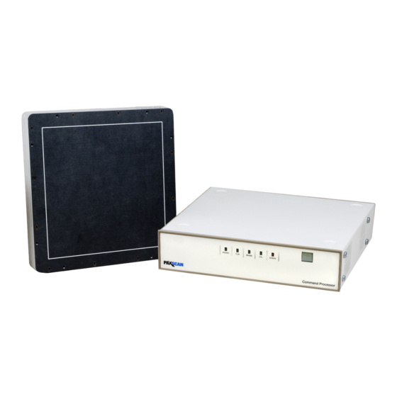
Summary of Contents for Varex Imaging PaxScan 2020X
- Page 1 PaxScan 2020X/2020XV/2121XV X-ray Detectors Before using the X-ray detector, be sure to read this manual thoroughly along with any other manuals for the software and other system components. Keep this manual where it is easily accessible. ®...
- Page 2 • In no event is Varex Imaging liable for direct, indirect, or consequential injury, damage, or loss of equipment operation time or image data arising from the use of the X-ray detector, its components, and/or accessories.
- Page 3 2020X/2020XV/2121XV X-ray Detectors For Your Safety To avoid personal injury or product damage, read this manual and all accompanying information carefully before handling, installing, or using the X-ray detector. Follow all instructions, warnings, and cautions in this manual and all warnings and cautions printed on the warning label.
- Page 4 Before You Begin 2020X/2020XV/2121XV X-ray Detectors Installation and Environment of Use The X-ray detector is intended to be installed, maintained, and used by WARNING qualified professional personnel who are trained and qualified in the installation, maintenance, and use of X-ray equipment. The detector should be mounted onto user-supplied equipment using WARNING the holes provided in the integral flange.
- Page 5 2020X/2020XV/2121XV X-ray Detectors Do not operate the X-ray detector in a location with the following Caution conditions: • Close to fluid or places where fluid is used • Close to heat sources, such as a heater • High temperature environment •...
- Page 6 Before You Begin 2020X/2020XV/2121XV X-ray Detectors Command Processor and Cables Be sure to turn OFF the power of the X-ray detector, including turning WARNING off the power supply before servicing, maintaining, connecting, or disconnecting the cables or accessories. Do not touch the power supply, X-ray detector, cable, connector, or any other electrical component or equipment with wet hands.
- Page 7 2020X/2020XV/2121XV X-ray Detectors Handling Never disassemble, modify, or alter the X-ray detector, its components, WARNING or accessories. Ignoring this warning may cause electrical shock and/or unknown hazards, which may result in severe personal injury, death, or substantial product damage. Changes or modifications not expressly approved by the manufacturer WARNING could void the user’s authority to operate the equipment.
- Page 8 Before You Begin 2020X/2020XV/2121XV X-ray Detectors If a Problem Occurs If any abnormal condition, such as smoke, fumes, or strange sounds, is WARNING evident, turn off the X-ray detector, turn off and unplug the power supply from the AC outlet, and immediately ask your establishment’s safety representative to contact your dealer, distributor, or device manufacturer.
-
Page 9: Table Of Contents
Table of Contents Scope ............. . . 1 Contraindication . - Page 10 Table of Contents 2020X/2020XV/2121XV X-ray Detectors Image Processor Control Unit ......... . . 26 Internal Power Supply .
- Page 11 Image Artifact Under Specific Conditions ....... . . 78 13.2 After-sales Service for Varex Imaging Products ......79 13.3 Disposing of the X-ray Detector.
- Page 12 Table of Contents 2020X/2020XV/2121XV X-ray Detectors This page intentionally left blank. www.vareximaging.com...
- Page 13 List of Figures Figure 1 Customer System ............6 Figure 2 Detector Surfaces and Features .
- Page 14 List of Figures 2020X/2020XV/2121XV X-ray Detectors Figure 31 ViVA – System Settings window ........51 Figure 32 Offset Calibration Initiation .
- Page 15 List of Tables Table 1 Abbreviations ............2 Table 2 Definition of Symbols .
- Page 16 List of Tables 2020X/2020XV/2121XV X-ray Detectors This page intentionally left blank. www.vareximaging.com...
-
Page 17: Scope
There are no contraindication situations Intended Use Varex Imaging digital X-ray Detectors and their accessories are components designed to be integrated into products by X-ray system manufacturers. Manufacturers are responsible for qualifying, validating, and certifying their products for their intended uses and meeting all applicable regulatory requirements. -
Page 18: Abbreviations
Cesium Iodide DPST Double-Pull Single-Throw Electromagnetic Compatibility IPCU Image Processor Control Unit LVDS Low Voltage Differential Signaling Original Equipment Manufacturer RoHS Restriction of Hazardous Substances Radio Frequency Software Developer Kit TOPS Two-Output Power Supply ViVA Varex Imaging Viewing Application www.vareximaging.com... -
Page 19: Definition Of Symbols
2020X/2020XV/2121XV X-ray Detectors Definition of Symbols Table 2 Definition of Symbols Symbol Description Temperature Limits Pressure Limits Humidity Limits On (power connection) Off (power disconnection) Protective Earth Ground Handle with Care Direct Current Alternating Current Authorized Representative in the European Community/European Union Manufacturer Date of Manufacture Consult Instruction for Use... - Page 20 2020X/2020XV/2121XV X-ray Detectors Table 2 Definition of Symbols (Continued) Do Not Discard with Domestic Waste European Union Mark of Conformity to Applicable Directives Underwriters Laboratory Safety Mark China RoHS environmentally friendly for 10 years Interference www.vareximaging.com...
-
Page 21: Standards And Regulations
European Union Electromagnetic Compatibility Directive Note: The 2020X/2020XV/2121XV does not contain any applied part. Note: The 2020X/2020XV/2121XV device is MDD Class IIa. Note: A Declaration of Conformity has been filed for this product and available upon request by contacting Varex Imaging Corporation. www.vareximaging.com... -
Page 22: Description Of The Detector And Command Processor
2020X/2020XV/2121XV X-ray Detectors Description of the Detector and Command Pro- cessor The detector is specifically designed to meet the needs of fluoroscopy and cone beam CT applications utilizing multiple sensitivity ranges. The X-ray Detector is mounted into the OEM’s mounting structure, such as a C-Arm, and is typically completely covered by the mounting and contrast-enhancing screen. -
Page 23: Table 4 Command Processor Component Boards
2020X/2020XV/2121XV X-ray Detectors The X-ray Detector operation is controlled using software commands via Ethernet. The set of possible X-ray Detector control operations is supplied to systems integrators in a C++ library of callable functions, in the form of a Win32 DLL. The communication interface is at the level of IP sockets. -
Page 24: Shipment Contents
Save all shipping containers in case a return is warranted. If there is any discrepancy, see “Section 13.2, After-sales Service for Varex Imaging Products” on page The contents of the shipment are: •... -
Page 25: Accessories
2020X/2020XV/2121XV X-ray Detectors Accessories The detector shall only be used with its approved Varex Imaging accessories and replacement parts. Product certification and warranty are rendered void if any modifications to the product is made, or any instruction, warning, or caution is not followed. It is important that the X-ray Detector is not directly connected to the installed network. - Page 26 Upon receipt, inspect the shipment and its contents against the Delivery Note enclosed with the shipment for evidence of damage or missing components. Save all shipping containers in case a return is warranted. If there is any discrepancy, please see “Section 13.2, After-sales Service for Varex Imaging Products” on page 79 www.vareximaging.com...
-
Page 27: Detector Surfaces And Features
2020X/2020XV/2121XV X-ray Detectors Detector Surfaces and Features For illustration purposes only, the detector is representative of the family of detectors. Figure 2 Detector Surfaces and Features Table 6 Detector Surfaces and Features Number Description Ground Lug Power Connector Power/Status Indicator LED Fiber Optic Port Mounting Holes Carbon Fiber Entrance Window... -
Page 28: Cables
2020X/2020XV/2121XV X-ray Detectors 8.3.1 Cables The cables used in the operation of the Detector and Command Processor. Figure 3 Cable Connections for the Detector and Command Processor Table 7 Cable Names and Descriptions Power Cable Provides 33V DC power to the detector from the Command Processor Fiber Optic Cable Provides a Fiber Optic link to the Command Processor... -
Page 29: Connecting The Cables
2020X/2020XV/2121XV X-ray Detectors Table 7 Cable Names and Descriptions (Continued) Camera Link Cable Connects to user’s workstation and provides real time video or 16-bit Video Cable Mains AC Power Cord Serial Cable (not pictured) Provides diagnostics and interface to load/update software to Command Processor 8.3.2 Connecting the Cables... -
Page 30: Detector Dimensions
2020X/2020XV/2121XV X-ray Detectors Note The serial cable must be the straight-through type, not the crossover type typically used between computers. The serial connection is used for diagnostics and loading new software into the Command Processor. This connection is often used during normal operation to monitor communications between the Command Processor and the Workstation. -
Page 31: Figure 5 2020X/2020Xv Detector Dimensions (Measured In Inches And Mm)
2020X/2020XV/2121XV X-ray Detectors Figure 5 2020X/2020XV Detector Dimensions (measured in inches and mm) Figure 6 2121XV Detector Dimensions (measured in inches and mm) www.vareximaging.com... -
Page 32: Figure 7 2121Xv Detector Dimensions (Measured In Inches And Mm)
2020X/2020XV/2121XV X-ray Detectors Figure 7 2121XV Detector Dimensions (measured in inches and mm) www.vareximaging.com... -
Page 33: Detector Specifications
2020X/2020XV/2121XV X-ray Detectors Detector Specifications Table 8 X-ray Detector Specifications Sensors 2020X 2020XV 2121XV Type Amorphous Silicon Amorphous Silicon Amorphous Silicon Scintillator Direct-Deposit CSI Direct-Deposit CSI Direct-Deposit CSI Pixel Matrix 1024 (v) x 1024 (h) 1024 (v) x 1024 (h) 1024 (v) x 1024 (h) Pixel Pitch 194 µm... - Page 34 2020X/2020XV/2121XV X-ray Detectors Table 8 X-ray Detector Specifications (Continued) Radiation Tolerance 2000 Gy (Active Area) 2000 Gy (Active Area) 2000 Gy (Active Area) Dynamic Range • • 94 dB Standard Modes 94 dB Standard 94 dB Standard Modes Modes • •...
-
Page 35: Environmental Considerations
2020X/2020XV/2121XV X-ray Detectors Environmental Considerations Environments outside the specification reduce the lifetime and may irreparably damage the Detector. Table 9 Environmental Considerations Category Limits Storage & Transport (ambient) -20º C to +70º C Storage and Operating Humidity Range (non-condensing) 10% to 90% Temperature Limit (as reported by internal sensors) +15°... -
Page 36: Input Current
2020X/2020XV/2121XV X-ray Detectors 8.7.2 Input Current Nominal current for any given input voltage within the above range is as follows: --------------- - input Peak current during configuration of the detector is given by: --------------- - input During initial power up, the X-ray Detector internal DC-DC converters present a low impedance load and it is therefore important that the power supply can maintain its limiting current with- out voltage drop. -
Page 37: Input Current
2020X/2020XV/2121XV X-ray Detectors 8.8.2 Input Current Nominal current for any given input voltage within the above range is as follows: --------------- - input Peak current during configuration of the detector is given by: 10.5W --------------- - input During initial power up, the X-ray Detector internal DC-DC converters present a low impedance load and it is therefore important that the power supply can maintain its limiting current without voltage drop. -
Page 38: Detector Mounting
2020X/2020XV/2121XV X-ray Detectors Detector Mounting The following warnings and cautions must be reviewed before mounting the X-ray Detector. The X-ray Detector is intended to be installed, maintained, and used by qualified professional personnel who are trained and qualified in the installation, maintenance, and use of X-ray equipment. -
Page 39: Command Processor Mounting
2020X/2020XV/2121XV X-ray Detectors 8.10 Command Processor Mounting The Command Processor can be rack mounted in a standard 3U (5.2” high) slot using optional rack mounting intended for a 19” wide rack. Optional sliding brackets are also available. Elevated operating ambient temperature: If installed in a closed or Caution multi-unit rack assembly, the operating ambient temperature of the rack environment may be greater than room ambient. -
Page 40: Power-On Sequence
2020X/2020XV/2121XV X-ray Detectors 8.10.1 Power-On Sequence A power switch, located at the rear of the command process, will connect/disconnect AC power to the unit. The power switch is a double pole single throw (DPST) panel mounted rocker switch, which makes and breaks both AC lines. The detector requires no action or intervention from the operator or the host system after power on or before power off. -
Page 41: Establishing Connection
2020X/2020XV/2121XV X-ray Detectors 8.10.2 Establishing Connection ViVA™ is the viewing application used to control the Command Processor. Varex Image Viewing and Acquisition (ViVA) is a non-commercial, graphical user interface (GUI) program that provides control over the detector out of the box. ViVA sends control commands to the Command Processor over an Ethernet connection. -
Page 42: Command Processor Hardware Configuration
2020X/2020XV/2121XV X-ray Detectors Command Processor Hardware Configuration This section describes the hardware configuration of the Command Processor. Motherboard The Motherboard is a PMC power PC-based computer. The motherboard contains flash memory into which the system software is loaded. The system software contains the operating system and the software program responsible for the control and communication of all Command Processor hardware. -
Page 43: Internal Power Supply
Varex imaging. If substitutions are made, these approvals are void and the image quality cannot be guaranteed. The internal Two-Output Power Supply (TOPS) has been designed for use in Varex Imaging products. It has a 5V output with remote sense used to internally power the Command Processor;... -
Page 44: Table 11 Pin Assignments Of The External Synchronization Port
2020X/2020XV/2121XV X-ray Detectors Table 11 Pin Assignments of the External Synchronization Port (Continued) Pin # Assignment Pin # Assignment OptMOut[2] OptMIn[2] OptPOut[3] OptPIn[3] OptMOut[3] OptMIn[3] OptPOut[4] OptPIn[4 OptMOut[4] OptMIn[4] OptPOut[5] OptPIn[5] OptMOut[5] OptMIn[5] OptPOut[6] OptPIn[6] OptMOut[6] OptMIn[6] OptPOut[7] OptPIn[7] OptMOut[7 OptMIn[7] OptPIn[8] OptPOut[8]... -
Page 45: Figure 9 Cable Generic Opto-Coupler Interface
2020X/2020XV/2121XV X-ray Detectors Figure 9 Cable generic opto-coupler interface The output pulls the signal line low with an open collector driver. The receiver side must provide and additional resistor to limit the current. The grounds of the two systems are not connected, and the interface should operate correctly for large common mode differences. -
Page 46: Table 13 Pin Default Hardware Handshaking Signals
2020X/2020XV/2121XV X-ray Detectors Table 12 Default Hardware Handshaking Interface (Continued) Signal Assignment Pin # Panel_Ready OptPOut[2] OptMOut[2] Reset OptPIn[2]] not currently implemented OptMIn[2] Radiation_Warning OptPIn[3]] not currently implemented OptMIn[3] OptPOut[3 Panel_Healthy OptMOut[3] Mode_Control_Bit0 OptPIn[4] not currently implemented OptMIn[4] Mode_Control_Bit1 OptPIn[5] not currently implemented OptMIn[5] Mode_Control_Bit2... -
Page 47: 16-Bit Video Output Signals
2020X/2020XV/2121XV X-ray Detectors Table 13 Pin Default Hardware Handshaking Signals (Continued) Event Causing Interruption Interpretation Signal from the OEM Controller. Indicates X-rays are at the proper intensity. This signal is asynchronous. Valid_XRays = True indicate that X-rays have begun to be produced at Valid_XRays the intended X-ray intensity. -
Page 48: Logic Levels
2020X/2020XV/2121XV X-ray Detectors 9.5.1 Logic Levels All signals are defined as LVDS (Low voltage differential signaling). Each individual signal contains a positive and a negative component. Thus, the twenty signals actually require forty connections. The recommended LVDS receivers are shown in Table 15 Table Note... -
Page 49: Frame Timing
2020X/2020XV/2121XV X-ray Detectors 9.5.2 Frame Timing A video frame consists of a real data frame inside a virtual frame. The virtual frame is increased from the real data frame by four strips of blanking: top vertical, bottom vertical, left horizontal and right horizontal, as illustrated in Figure 10 Figure 10 Frame timing... -
Page 50: Signal Vsync
2020X/2020XV/2121XV X-ray Detectors Table 17 describes the timing specifications for Pix Table 17 Timing Specifications Model Units = 1/ tclk jitter (pp) duty cycle 12.5 high 12.5 9.5.3 Signal V sync Note Data Valid must remain high during the valid image data frame. Thus, bursting of data with gaps is not allowed. -
Page 51: Signal Datavalid
2020X/2020XV/2121XV X-ray Detectors 9.5.5 Signal DataValid DataValid defines the real image data within the virtual frame. DataValid is high during blanking and low when valid image data is present on the data lines. Refer to Figure 11 through Figure 15 for detector User_Sync Timing Diagram. -
Page 52: Default Mode
2020X/2020XV/2121XV X-ray Detectors Figure 14 Timing Overview Figure 15 Detailed view of one HSYNC and Data_Valid Default Mode Mode 0 is the normal default mode, although this can be configured to meet the customer’s specific application requirements. The default mode will be invoked automatically under the following conditions: •... -
Page 53: Recursive Filter
2020X/2020XV/2121XV X-ray Detectors Recursive Filter A temporal (recursive) filter is used to reduce noise in low dose fluoroscopic applications, at the expense of increased image lag. The intrinsic lag of the a-Si panel is roughly 4% in the first frame, but can remain at the 1% level for seconds. -
Page 54: Connector And Cable Pin-Outs
2020X/2020XV/2121XV X-ray Detectors 9.11 Connector and Cable Pin-outs Two connector pin-outs and cables are supported. The pin-out for the supported connectors are shown in Figure Figure 16 LVDS (black/white) and Camera Link (red/black/blue) pin assignments www.vareximaging.com... -
Page 55: Lvds
2020X/2020XV/2121XV X-ray Detectors 9.11.1 LVDS The connectors at both the transmitter and the receiver are AMP 50 pin SCS-II receptacles, right-angle or vertical. The cable is a standard 50 conductor SCSI-II cable with male plugs at both ends. The pin out for the connectors is shown in Figure 16. -
Page 56: Timing
2020X/2020XV/2121XV X-ray Detectors 9.11.4 Timing The Command Processor will lock the generation of all internal clocks to the rising edge of the User Synchronization signal provided by the user. Assuming the detector is using the maximum readout rate, which is approximately 32 usec/line, the requirements for User_Sync are: Table 18 Frequency Requirements for User_Sync Mode... -
Page 57: Pulsed X-Ray Beam Applications
2020X/2020XV/2121XV X-ray Detectors 9.12 Pulsed X-ray Beam Applications Asynchronous X-ray exposure can cause additional noise and interference appearing as stripes of different brightness, which occur at points throughout the image corresponding to the beam ON times. To avoid this interference, X-ray beam synchronization is used. Note A frame is composed of a panel readout period and a vertical blanking period. -
Page 58: Modes Of Operation
2020X/2020XV/2121XV X-ray Detectors 10.0 Modes Of Operation The detector supports a number of modes of operation as defined in Table 19. In general, there is a trade-off between varying operation modes of resolution, field of view, frame rate, and noise. The sensitivity of the X-ray Detector is optimized to match the X-ray dose used in each mode. -
Page 59: Operation States
2020X/2020XV/2121XV X-ray Detectors Table 20 2121XV Operational Mode Examples Frame Pixel Integration Image Active Acquisition Mode Frame Size Rate Binning Capacitor Area Frame Size Type (Hz) High- 2 x 2 0.5pF Full Field 512 x 512 502 x 502 Continuous Sense Fluoro Normal-... -
Page 60: System Software
2020X/2020XV/2121XV X-ray Detectors 11.0 System Software The software package provides the application program interface (API) to the detector, allowing control and image transfer functionality through the Command Processor (see the Software Interface Document for more information). The software package also includes ViVA™ software—the viewing application used to perform X-ray Detector calibration, detector setup, image acquisition, and image corrections in a Windows PC environment. -
Page 61: Figure 20 Installation
2020X/2020XV/2121XV X-ray Detectors An Installer window will appear, click Next. Figure 20 Installation Follow the on-screen prompts, once complete, click Finish. Figure 21 Installation Complete www.vareximaging.com... -
Page 62: Detector Files Installation
2020X/2020XV/2121XV X-ray Detectors 11.2 Detector Files Installation The detector files are specific to the panel providing calibration and configuration files. Installation of the software and detector files is briefly discussed in the following sections. Refer to the ViVA™ Online help for assistance operating ViVA and for complete details on software installation refer to Detector Install Guide documentation included in the software package. -
Page 63: Figure 23 Choose Install Location Window
2020X/2020XV/2121XV X-ray Detectors Figure 23 Choose Install Location window To change the Destination Folder, click Browse, then select the new install location. If no change, click Install to begin installation. Once the software is done installing, the window displays the following. Figure 24 2020X/2020XV/2121XV detector setup is complete www.vareximaging.com... -
Page 64: Link To The Detector
2020X/2020XV/2121XV X-ray Detectors 11.3 Link to the Detector Click the ViVA icon. The application launches. Figure 25 The ViVA icon Click Acquisition from the menu bar, Click Open Ethernet Link. Figure 26 Open Ethernet Link An alternate method to link the detector is to click the Mode Drop Down Menu and Click Link to Command Processor. -
Page 65: Viva Mode And System Settings
2020X/2020XV/2121XV X-ray Detectors The detector will link with a mode populated in the Mode Drop Down Menu. Figure 28 Detector Linked 11.4 ViVA Mode and System Settings Perform the following steps to adjust the ViVA mode settings. Ensure the desired Mode is selected in the Mode drop-down. Figure 29 Mode Drop-Down Menu www.vareximaging.com... -
Page 66: Figure 30 Viva - Mode Settings Window
2020X/2020XV/2121XV X-ray Detectors Select Acquisition > Mode Settings from the menu. A ViVA – Mode Settings window opens. Figure 30 ViVA – Mode Settings window Make the necessary adjustments to Calibration Setup settings, located in the lower left corner as displayed in Figure Select the number of Calibration Frames to be used. -
Page 67: Figure 31 Viva - System Settings Window
2020X/2020XV/2121XV X-ray Detectors Click Acquisition > System Settings from the menu to open the ViVA – System Settings window. Figure 31 ViVA – System Settings window Under Image Corrections (right side of ViVA – System Settings window), select the desired options by checking the box. -
Page 68: Calibration Procedures
2020X/2020XV/2121XV X-ray Detectors 11.5 Calibration Procedures The IPU in the Command Processor corrects for gain, offset and analog variation between individual pixels as well as globally across the image. This non-uniformity compensation requires that a gain reference image and an offset reference image be resident in the Command Processor’s high speed SDRAM memory prior to imaging procedures. -
Page 69: Offset Calibration Steps
2020X/2020XV/2121XV X-ray Detectors • A different offset reference image is necessary for each operating mode, therefore it is important to update the offset data for each of the operating modes. • If the prepare signal on the Command Processor’s external synchronization port is asserted, the detector is able to abandon an ongoing offset calibration with no loss in pre-calibration image quality. -
Page 70: Figure 33 Viva - Offset Calibration Progress Windows
2020X/2020XV/2121XV X-ray Detectors An Accumulating Dark Frames window appears, followed by an offset calibration acquisition completion. Offset calibration is required for each additional detector mode, respectively. See Figure 33 Figure 33 ViVA – Offset Calibration Progress windows Since the offset characteristics of the X-ray Detector vary during WARNING normal operation, the offset reference image must be updated at least every two to five minutes while the X-ray Detector is warming up, and... -
Page 71: Gain Calibration
2020X/2020XV/2121XV X-ray Detectors 11.5.3 Gain Calibration To compensate for non-uniformities in the X-ray Detector, a gain reference image (flat field) is used by the Corrections module as required to correct all images. The flat field image must be captured by the Command Processor prior to acquiring images. The process of capturing the flat field image is known as Gain Calibration. - Page 72 2020X/2020XV/2121XV X-ray Detectors Note Accumulate a minimum of 128 frames for fluoroscopic modes and 32 frames for full-resolution modes. For low frame rates such as one frame per second, this may be too long a period. In such cases, it may be necessary to lower the number of calibration frames to a more tolerable time period, not going below eight frames.
-
Page 73: Gain Calibration Steps
2020X/2020XV/2121XV X-ray Detectors 11.5.4 Gain Calibration Steps Perform the following steps to perform gain calibration for all modes: Ensure the desired detector imaging mode appears in the acquisition Mode Drop Down Menu. Figure 34 Mode Drop Down Menu Select Acquisition > Gain Calibration. Figure 35 Gain Calibration Initiation www.vareximaging.com... -
Page 74: Figure 36 Gain Calibration Window
2020X/2020XV/2121XV X-ray Detectors A Gain Calibration window opens. Figure 36 Gain Calibration window Remove all objects from the X-ray beam. Initiate X-ray exposure. Press Continue. The detector begins acquiring flat field images. Figure 37 Gain Calibration Progress window www.vareximaging.com... -
Page 75: Figure 38 Gain Calibration Complete
2020X/2020XV/2121XV X-ray Detectors When the flat field accumulation completes, terminate the X-ray beam. Press Continue in the Gain Calibration window. Dark field accumulation begins with progress status shown in the Gain Calibration window. Fluoroscopic gain calibration completes with display of the gain calibration statistics. Note Gain median count should be between 20000 +/- 10000. -
Page 76: Defective Pixel Maps
2020X/2020XV/2121XV X-ray Detectors Note Replacement of the X-ray tube will require a new gain calibration to be performed. Note It is recommended to accumulate a minimum of 32 frames for gain calibration for optimal image quality. However, the actual number of calibration frames used must be determined solely by the system integrator depending upon their specific performance requirements. -
Page 77: Analog Offset Calibration
2020X/2020XV/2121XV X-ray Detectors 11.5.6 Analog Offset Calibration Analog Offset calibrations are determined during imaging system configuration at the factory, or if a new mode configuration file is loaded. Analog Offset calibration reduces non-uniform pixel offsets corrected by differences in the readout components located in the detector. - Page 78 2020X/2020XV/2121XV X-ray Detectors After each analog offset calibration, the mode must have the gain WARNING calibration performed again. Click Yes, the system will launch the gain calibration process. Note Analog Offset Calibration requires no X-rays during the calibration procedure. Note The system should be powered ON for at least two hours prior to performing an Analog Offset Calibration.
-
Page 79: Image Acquisition
2020X/2020XV/2121XV X-ray Detectors 11.6 Image Acquisition Once offset and gain calibration are performed, ViVA is ready to acquire images. 11.6.1 Single Image Acquisition Perform the following steps to acquire images: In the ViVA window, select desired mode from the Mode Drop Down Menu. Figure 41 Mode Drop Down Menu Click Acquire Image. -
Page 80: Figure 43 Viva - Fluoroscopic Acquisition Window
2020X/2020XV/2121XV X-ray Detectors A Fluoroscopic Acquisition window opens. Figure 43 ViVA – Fluoroscopic Acquisition window Click Stop to acquire an image. Upon first acquisition, a window for user comments appears. Figure 44 User Comment window Enter user comments if necessary. Click OK. -
Page 81: Real-Time Fluoroscopy Normal/Full Resolution Mode
2020X/2020XV/2121XV X-ray Detectors 11.6.2 Real-time Fluoroscopy Normal/Full Resolution Mode Note For real time Fluoroscopy operation, a bitflow camera link or a bitflow LVDS card must be installed into the host computer, and video data cable (LVDS or CameraLink) must be connected between the Command Processor and the Bitflow card. -
Page 82: Figure 47 Capture Data
2020X/2020XV/2121XV X-ray Detectors Click OK. If no comments are entered, Click Cancel to continue. Following acquisition, a message box appears, providing active image capture data. Figure 47 Capture Data Click OK. Save the acquired image by selecting File from the menu bar and click on Save As. Select the seq/avi file format. -
Page 83: Configuration: Hostdown Utility Applications
2020X/2020XV/2121XV X-ray Detectors 11.7 Configuration: Hostdown Utility Applications The following paragraphs discuss Hostdown utility applications. 11.7.1 Updates via Serial Link The Hostdown Utility Application is used for any software program update, change or revisions. The system configuration software package used to configure the Command Processor consists of the following: •... -
Page 84: Figure 48 Host Download Window
2020X/2020XV/2121XV X-ray Detectors 11.7.2.1 Connecting to the Command Processor Power off the Command Processor. Connect your computer com port to the Command Processor’s serial 1 port. On Workstation, run the Hostdown.exe program located in the Command Processor directory in the detector Software release folder. Double - click Hostdown. -
Page 85: Figure 50 Download Window
2020X/2020XV/2121XV X-ray Detectors Click OK. Target Info populates in the Host Download window. 11.7.2.2 Download to Target There are several types of configuration files which reside permanently in the flash memory of the Command Processor. The files listed in Section 11.7.1 can be replaced by downloading new versions over a serial link using the utility application hostdown.exe. -
Page 86: Ip Addresses
2020X/2020XV/2121XV X-ray Detectors 11.7.2.3 Change Target’s Time Choose Target Commands > Change Target’s time. A window appears. Figure 51 Change Target’s Time Of Day Enter in the required date and time. Click Set Time Now. Note For additional assistance operating ViVA™, use the ViVA Online help documentation. -
Page 87: Figure 52 Change Target's Ip Address
2020X/2020XV/2121XV X-ray Detectors 11.7.3.1 Setting the Command Processor IP Address Perform the following steps to set the Command Processor IP address: From the menu bar, select Target Commands > Change Target’s IP Address. A Change Target’s IP Address window appears. Figure 52 Change Target’s IP Address Enter the new IP address. -
Page 88: Figure 53 Workstation Address Information
2020X/2020XV/2121XV X-ray Detectors 11.7.3.2 Setting Workstation IP Address This procedure assumes that the workstation uses Windows NT as the operating system. Perform the following steps to update the workstation IP address. Select Start > Settings > Control Panel. Double-click the Network icon. Click the Protocols tab. -
Page 89: Maintenance
2020X/2020XV/2121XV X-ray Detectors 12.0 Maintenance In principle the X-ray Detector assembly is maintenance-free; however, it is important that all correction files are regularly updated and used for image processing. In some applications, it is advantageous to update the offset correction file directly before each image. Although the a-Si X-ray Detectors are resistant to X-rays, they can exhibit degradation over time when exposed to high X-ray dose environments. -
Page 90: Cleaning The X-Ray Detector
2020X/2020XV/2121XV X-ray Detectors 12.1.2 Cleaning the X-ray Detector To clean the X-ray Detector: Turn off the X-ray Detector and detach the power and communication tethered cable, if applicable. Locate and read the cleaning instructions specified on the product label. Follow the product instructions for cleaning. -
Page 91: Command Processor Fuse Replacement
2020X/2020XV/2121XV X-ray Detectors 12.2 Command Processor Fuse Replacement Perform the following steps to replace the Command Processor fuse. Two replaceable fuses at the power inlet module protect the command WARNING processor from overload due to a short circuit condition. For continued protection against fire risk, replace with the same type and rating of fuse. -
Page 92: Troubleshooting
2020X/2020XV/2121XV X-ray Detectors 13.0 Troubleshooting Table 21 Problems and Solutions Problem Solution Detector causes Electro-Magnetic 1. Reorient or relocate the receiving device. Interference 2. Increase the separation between the equipment. 3. Consult the manufacturer or field service technician for help. Acquired image is Non-linear or 1. - Page 93 2020X/2020XV/2121XV X-ray Detectors Table 21 Problems and Solutions (Continued) Acquired images show defective 1. Ensure that the tube dose is set to the correct settings. pixels 2. Acquire another image at the recommended median count as stated in Section 11.5.3. 3.
-
Page 94: Image Artifact Under Specific Conditions
2020X/2020XV/2121XV X-ray Detectors Table 21 Problems and Solutions (Continued) ViVA software freezes Restart the computer and re-launch the ViVA software. ViVA error message 1. Email the error log file generated to: flatpanel.warranty@vareximaging.com. This log file is normally found at C:\users\{username}\AppData\Local\ crashdumps\viva.log Detector dropped 1. -
Page 95: After-Sales Service For Varex Imaging Products
This product should not be mixed with other commercial waste for disposal. The Varex Imaging product may be attached as part of a component to other manufacturers’ systems. These other manufacturers are directly responsible for the collection and processing of their own waste products under the terms of the WEEE Directive. -
Page 96: Safety
2020X/2020XV/2121XV X-ray Detectors 14.0 Safety This section describes electromagnetic safety. 14.1 Electro-Magnetic Interference Varex X-ray Detectors generate, use, and radiate radio frequency (RF) energy. If not installed and used in accordance with the instructions, they may cause harmful interference to other devices or may be affected by other equipment in the vicinity. -
Page 97: Electromagnetic Emissions
2020X/2020XV/2121XV X-ray Detectors 14.3 Electromagnetic Emissions Electromagnetic emissions and immunity levels are selected according to intended use in a professional healthcare facility and home healthcare environments. Table 23 Radiated/Conducted Emissions, Harmonics, Voltage, Fluctuation, & Flicker IEC 60601-1-2 Emissions test Compliance Electromagnetic environment test level RF conducted... -
Page 98: Electromagnetic Immunity
2020X/2020XV/2121XV X-ray Detectors 14.4 Electromagnetic Immunity Table 24 Transient/Burst, Surge, Voltage Variation, Magnetic Fields IEC 60601-1-2 Immunity test Compliance Electromagnetic environment test level Electrostatic ± 8 kV ± 8 kV Floors should be wood, concrete, or discharge (ESD) contact discharge contact discharge ceramic tile. -
Page 99: Rf Immunity
2020X/2020XV/2121XV X-ray Detectors 14.5 RF Immunity Table 25 Conducted / Radiated RF IEC 60601-1-2 Immunity test Compliance Electromagnetic environment test level Conducted RF 3 Vrms 3 Vrms Portable and mobile RF communications 150 kHz to 80 150 kHz to 80 equipment should be used no closer to any part IEC 61000-4-6 of the detector than the recommended... -
Page 100: Separation Distances
2020X/2020XV/2121XV X-ray Detectors Note At 80 MHz and 800 MHz, the higher frequency range applies. Note These guidelines may not apply in all situations. Electromagnetic propagation is affected by absorption and reflection from structures, objects and people. 14.6 Separation Distances Recommended distances for portable and mobile RF communications equipment. -
Page 101: Degraded Electromagnetic Compatibility
2020X/2020XV/2121XV X-ray Detectors Note These guidelines may not apply in all situations. Electromagnetic propagation is affected by absorption and reflection from structures, objects and people. 14.7 Degraded Electromagnetic Compatibility The use of accessories, transducers, and cables other than those WARNING specified or provided by the manufacturer of this equipment could result in increased electromagnetic emissions or decreased electromagnetic immunity of this equipment and result in improper... - Page 102 2020X/2020XV/2121XV X-ray Detectors This page intentionally left blank. www.vareximaging.com...
- Page 103 Index Numerics 16-bit Video Cable Defect Maps 2020X/2020XV Mounting Holes, Front Defective Pixels 2020X/2020XV Mounting Holes, Rear Definition of Symbols 2121XV Mounting Holes, Front Detector Files Installation 2121XV Mounting Holes, Rear Detector Mounting Detector Specifications Dimensions, Detector Accessories Disposal Alerts and Notes, Meaning of Alternative Power Supply Electrical Shock Protection Energy Range...
- Page 104 Index 2020X/2020XV/2121XV X-ray Detectors In-Warranty Obtain RMA Number Link to the Detector Out-of-Warranty LVDS Repair Settings, Mode Settings, System Mains Sharps Maintenance Shipment Contents viii Maintenance and Inspection Safety Note Shock, Protection Meaning of Alerts and Notes Signals Modes of Operation Specifications Mounting, Command Processor Active Area...
- Page 105 2020X/2020XV/2121XV X-ray Detectors This page intentionally left blank.
- Page 106 ©2024 Varex Imaging All rights reserved. The Varex Imaging logo and design are registered trademarks of Varex Imaging or its subsidiaries, in the United States and other countries. Paxscan is a registered trademark and ViVA is a trademark of Varex Imaging. All other trademarks not owned by Varex Imaging or its subsidiaries that are depicted herein are the property of their respective owners.
Need help?
Do you have a question about the PaxScan 2020X and is the answer not in the manual?
Questions and answers