Sign In
Upload
Manuals
Brands
Utah Scientific Manuals
Switch
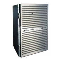
Utah-400 iP
Utah Scientific Utah-400 iP Switcher Manuals
Manuals and User Guides for Utah Scientific Utah-400 iP Switcher. We have
4
Utah Scientific Utah-400 iP Switcher manuals available for free PDF download: Setup & Operation, System Setup And Operations, Set Up And Operation Manual
UTAH SCIENTIFIC Utah-400 iP Setup & Operation (161 pages)
Digital Routing Switcher
Brand:
UTAH SCIENTIFIC
| Category:
Switch
| Size: 4 MB
Table of Contents
Table of Contents
9
In this Guide
15
Introduction
15
Conventions
17
Abbreviations
18
Terms
19
Routing Switcher Basics
20
Switching Matrix
21
Signal Levels
22
The Utah-400 Routing Matrix
23
Sample Configurations
25
System Configurations
25
Hardware Installation
27
In this Chapter
27
Unpacking and Inspection
28
Installing Physical Equipment
29
Installing the Utah-400 Digital Routing Switcher
29
Mounting Equipment in Rack Frames
29
Installing the MX-Bus Cables
33
Interconnecting the SC-4 and Utah-400 Frames
33
Connecting the AES Reference Signal
35
Determining and Setting Router Signal Levels
35
Offset Switch
37
Installing the Analog Audio Input and Output Cables
42
Connecting and Disconnecting Power
47
DC Connectivity
48
Pre Power-Up Checks
49
Hardware Checkout
50
In this Chapter
51
Utah 400 SC-4 Control
52
Module Array - Panel Front
54
Alarm Indication
55
Ethernet and RS-422 Connection
55
Operation
55
Crosspoint Cards Maintenance
56
Crosspoint Card Removal and Replacement
57
Input and Output Card Removal and Replacement
57
Fan Service
58
Power Supply
59
In this Chapter
61
Utah-400 Components
61
SD Video Input
62
Video Input
62
Analog to Digital
63
Multi-Rate Input
63
Reclocking Input Expansion Card
66
UTAH-400 3G Input Card
67
SD-Output
69
Video Output Boards
69
Digital Video to Analog Converter Output Card
70
HD-Output (Multi-Rate Output Card)
70
Multi-Rate Output Board
72
Control Description
74
UTAH-400 3G Output Board
75
Fiber Interface - (Optional)
77
Specification Detail
78
Fiber Output LED Indications
79
Indicators
81
Video Crosspoint Board (Redundant)
81
Dip Switches
83
Monitor Output
83
MX Bus
83
Rear Panel Considerations
83
Analog Blackburst
84
Power Supplies
84
LED Indications
85
Audio Input
87
Audio Input Board
87
Audio Output
88
Audio Output Board
88
Deluxe Output Board
89
Board Indicators
90
Deluxe Output Module
91
DAC Output Module
93
ADC Input Module
95
Audio Crosspoint Board
97
Front Edge Card Indicators (Left Bank)
98
Front Edge Card Indicators (Right Bank)
98
Audio Crosspoint Adjustments
99
Time Base Module
99
Fuses
102
Test Points (Front of Crosspoint Card)
103
In this Chapter
105
Troubleshooting
105
Main Troubleshooting Chart
106
Subsystem Level Troubleshooting
106
Video Subsystem Troubleshooting Table
108
Audio Subsystem Troubleshooting Table
109
Power Subsystem Troubleshooting Table
110
Power Supply Alarms
110
Control Subsystem Troubleshooting Table
111
System Controller Alarms
112
Control Panel Troubleshooting
113
Ethernet Panels
113
UNET Panels
113
In this Appendix
115
Specifications
115
Input Power and DC Power Specifications
116
Power
116
Digital Video
117
Digital Video Specifications
117
Digital Audio
118
Digital Audio Specifications
118
High Definition SDI Video
119
High Definition SDI Video Specifications
119
Reference
119
Reference Specifications
119
Control
120
Control Specifications
120
Alarm Specifications
121
Alarms
121
Physical
122
Physical Specifications
122
Regulatory
122
Regulatory Specifications
122
Connector Suppliers
123
Connector Suppliers and USI Part Numbers
123
The Debug Port
125
The Debug Cable
126
Using the Debug Port
127
Main Menu Display
128
Startup Display
128
FPGA Memory Status
129
Verifying the Software Version
129
Checking the Router Crosspoint Status
130
IO Card Information
131
Checking Input / Output Card Information
133
IO Information - Full Display
134
Hardware Status
135
External PS Status
136
Crosspoint Voltage (Levels
138
DC CONV Readings
138
The Utah-400 Digital Audio Breakout Panel
139
Description of the AES Breakout Panel
140
Installation of the AES Breakout Panel
140
Scope
140
The AES Breakout Panel Kit
140
Application
143
Label Instructions for the Utah-400 Breakout Panel Scope
143
Crosspoint Card Firmware Upgrade
145
Process
145
Scope
145
MADI Board Configuration
148
MADI IX8 / MADI IX16 Input Modules
148
MADI Input Slot Board Installation
150
MADI Input Rear Panel Cabling
151
MADI OX8 / MADI OX16 Output Module
152
MADI Output Slot Board Installation
155
MADI Output Rear Panel Cabling
156
Advertisement
Utah Scientific Utah-400 iP System Setup And Operations (146 pages)
Digital Routing Switcher 64x64 Systems
Brand:
Utah Scientific
| Category:
Switch
| Size: 4 MB
Table of Contents
Copyrights and Trademarks
2
Declaration of Conformity
3
Table of Contents
9
CHAPTER 1 Introduction
13
In this Guide
13
Conventions
14
Abbreviations
15
Terms
16
Routing Switcher Basics
17
Switching Matrix
18
Signal Levels
19
The Utah-400 Routing Matrix
20
Introducing the Utah-400 Digital Routing Switcher
22
System Configurations
24
CHAPTER 2 Hardware Installation
27
In this Chapter
27
Unpacking and Inspection
28
Installing Physical Equipment
29
Mounting Equipment in Rack Frames
29
Installing the Utah-400 Digital Routing Switcher
29
Installing the MX-Bus Cables
32
Interconnecting the SC-4 and Utah-400 Frames
32
Determining and Setting Router Signal Levels
35
Installing the Video Input and Output Signals
39
Installing the Analog Audio Input and Output Cables
42
Connecting and Disconnecting Power
47
AC Connection
47
DC Connectivity
48
Crosspoint Leds
49
If no Led's on the Crosspoint Board Are on
49
UTAH-64X Read out / Layout
50
Hardware Checkout
51
CHAPTER 3 Control System Interconnection
54
SC-4 Based Connections
54
Internal SC-400 Based Connections
55
SC-400 Control Board
57
The SC- 400 LED Indications
57
SC-400 Jumper Settings
58
SC-400 Dipswitch Setting
58
Operation
59
Input and Output Card Removal and Replacement
59
Crosspoint Card Removal and Replacement
60
Operation
61
Fan Service
61
Rear Panel Overview
61
SC-400 - Specific Connections
62
U-Net Connector
65
U - NET Cabling
66
CHAPTER 4 Utah-400 Components
69
In this Chapter
69
Video Input Boards
70
SD Video Input
70
Multi-Rate Input
70
Analog to Digital
71
Reclocking Input Expansion Card
73
UTAH-400 3G Input Card
74
Video Output Boards
76
SD-Output
76
HD-Output (Multi-Rate Output Card)
77
Digital Video to Analog Converter Output Card
77
Multi-Rate Output Board
79
Control Description
80
UTAH-400 3G Output Board
81
Fiber Interface
83
Specification Detail
84
Fiber Output LED Indications
85
Crosspoint Board
87
User Controls
88
Indicators
88
Fuses
91
Test Points (Front of Crosspoint Card)
92
Audio Chassis - Basic Layout Chassis Assembly
93
Audio Chassis - Basic Layout
93
Deluxe Output Module
94
DAC Output Module
96
ADC Input Module
99
Crosspoint Board
101
Power Supply
105
LED Indications
105
CHAPTER 5 Troubleshooting
107
In this Chapter
107
Subsystem Level Troubleshooting
108
Main Troubleshooting Chart
108
Video Subsystem Troubleshooting Table
110
Power Subsystem Troubleshooting Table
111
Power Supply Alarms
111
Control Subsystem Troubleshooting Table
112
System Controller Alarms
113
Control Panel Troubleshooting
114
Specifications
115
APPENDIX A Specifications
115
In this Appendix
115
This Appendix Provides Detailed Lists of All System Audio, Video, Control
116
Power
116
Input Power and DC Power Specifications
116
Digital Video
117
High Definition SDI Video
118
Reference
118
Control
119
Alarms
119
Physical
120
Regulatory
120
Connector Suppliers and USI Part Numbers
121
The Debug Port
123
APPENDIX B the Debug Port
124
This Appendix Contains the Following:
124
UT-400/64 Firmware
124
Menu Items
124
Status
124
The Debug Cable
125
Using the Debug Port
126
Startup Display
127
Main Menu Display
127
FPGA Memory Status
128
Verifying the Software Version
128
Checking the Router Crosspoint Status
129
Checking Input / Output Card Information
132
IO Information - Full Display
133
IO Card Information - Locator Diagram
134
Hardware Status Display
135
APPENDIX C the Utah-400 Digital Audio Breakout Panel
137
Scope
137
The AES Breakout Panel Kit
137
Description of the AES Breakout Panel
137
Installation of the AES Breakout Panel
138
Label Instructions for the Utah-400 Breakout Panel
140
Scope
140
Application
140
The Utah-400 Digital Audio Breakout Panel
137
UTAH SCIENTIFIC Utah-400 iP Set Up And Operation Manual (94 pages)
Data Router
Brand:
UTAH SCIENTIFIC
| Category:
Switch
| Size: 1 MB
Table of Contents
The UTAH-400 Data Router
2
Copyrights and Trademarks
2
Notice
2
Declaration of Conformity
3
Important Safeguards and Notices
4
Company Information
6
Warranty Policies
7
Table of Contents
9
Introduction
11
In this Guide
11
How to Use this Guide
12
Conventions
12
Abbreviations
13
Terms
13
Routing Switcher Basics
15
Switching Matrix
15
Signal Levels
16
The Utah-400 Data Routing Matrix
17
Introducing the Utah-400 Data Routing Switcher
20
System Configurations
21
Data Router Functional Description
22
Hardware Installation
29
In this Chapter
29
Unpacking and Inspection
30
Recommended Unpacking Method
31
Installing Physical Equipment
31
Mounting Equipment in Rack Frames
31
Installing the MX-Bus Cables
35
Interconnecting the SC-4 and Utah-400 Frames
35
Determining and Setting Router Signal Levels
37
Installing the Data Matrix Port Cables
41
Modular RJ-45 Serial Port Pin Assignments
43
SMPTE-207M Serial Port Information
44
D-Subminiature Adaptors
45
Data Matrix Signal-Line Terminations
47
Matrix Expansion Facilities
52
SMPTE Alarm Facility
55
Connecting and Disconnecting Power
57
Hardware Checkout
58
System Operations
61
Data Port Indicators
62
Main Board Status Indicators
65
Main Board Scangate Indicators
67
Power Supply Status Indicators
68
Reset Switch
70
FPGA Control Board
72
Troubleshooting
75
In this Chapter
75
Subsystem Level Troubleshooting
76
Main Troubleshooting Chart
76
Video Subsystem Troubleshooting Table
78
Audio Subsystem Troubleshooting Table
79
Power Subsystem Troubleshooting Table
80
Power Supply Alarms
81
Control Subsystem Troubleshooting Table
82
System Controller Alarms
83
Control Panel Troubleshooting
84
Diagnostic Loopback Functions
85
Checking and Replacing Fuses
88
Advertisement
UTAH SCIENTIFIC Utah-400 iP System Setup And Operations (33 pages)
iP Routing Switcher
Brand:
UTAH SCIENTIFIC
| Category:
Switch
| Size: 0 MB
Table of Contents
Copyrights and Trademarks
2
Declaration of Conformity
3
Table of Contents
9
Introduction
12
Overview
12
Features
12
Switch View
13
Ut-400-Ipw/Rcp
13
Panel View
14
Panel Cabling
15
Installation
17
CHAPTER 2 Installation
18
Cable Orientation for Non-CP Switch
18
Rack Mounting
19
Installing the Utah-400 Ip Components
19
Connections
20
Ethernet Cable Connections
20
Other Wiring Rules
20
Stacking Cable Connections
21
Console Port Connection
22
System Management
23
Introduction
24
CHAPTER 3 System Management
25
Remote Control Panel
25
Remote Control Panel Usage - Status
25
Remote Control Panel Usage - Control
25
Telnet / Diagnostic Interface
26
Telnet / Diagnostic Command Structure
26
Web Management
28
Detailed Configuration Scenarios
30
Qos
30
Solution
30
Operation
30
Port Aggregation Operation
31
Aggregation Mode Checkboxes
31
Aggregation Group Definitions
31
VLAN Configuration
31
Private VLAN Configuration
31
Advertisement
Related Products
UTAH SCIENTIFIC UTAH-200
UTAH SCIENTIFIC Utah-400 XL
UTAH SCIENTIFIC Utah-400 2 Series
UTAH SCIENTIFIC UTAH-100/UDS XY-Panel
UTAH SCIENTIFIC UHD 12G
Utah Scientific UTAH-100 UDS-288
UTAH SCIENTIFIC UTAH-100/UDS 10x10
UTAH SCIENTIFIC UTAH-100/UDS 20x20
UTAH SCIENTIFIC UTAH-100/UDS XY
UTAH SCIENTIFIC UTAH-100/UDS 8X32 DA
Utah Scientific Categories
Switch
Control Panel
Network Router
Control Systems
Amplifier
More Utah Scientific Manuals
Login
Sign In
OR
Sign in with Facebook
Sign in with Google
Upload manual
Upload from disk
Upload from URL