Sign In
Upload
Manuals
Brands
UTAH SCIENTIFIC Manuals
Switch
Utah-400 2 Series
UTAH SCIENTIFIC Utah-400 2 Series Routers Manuals
Manuals and User Guides for UTAH SCIENTIFIC Utah-400 2 Series Routers. We have
1
UTAH SCIENTIFIC Utah-400 2 Series Routers manual available for free PDF download: Setup & Operation
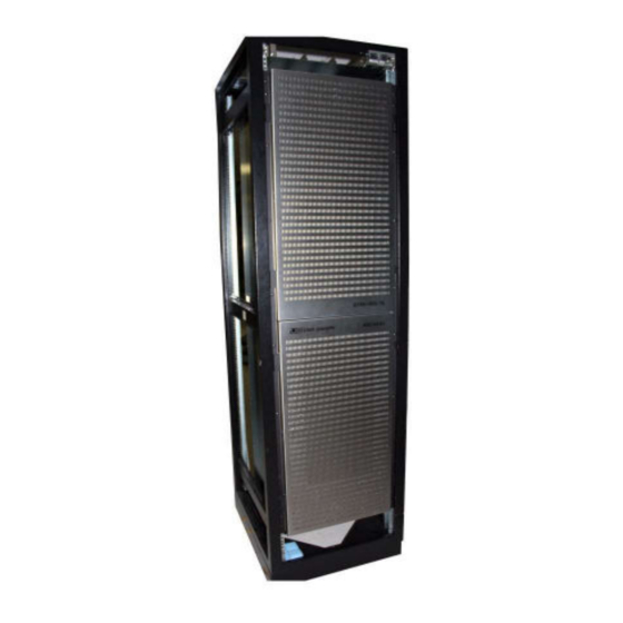
UTAH SCIENTIFIC Utah-400 2 Series Setup & Operation (288 pages)
Brand:
UTAH SCIENTIFIC
| Category:
Switch
| Size: 8 MB
Table of Contents
Introduction
9
Table of Contents
9
CHAPTER 1 Introduction
17
Conventions
19
Abbreviations
20
Terms
21
Routing Switcher Basics
22
Switching Matrix
23
Signal Levels
24
The Utah-400 Routing Matrix
25
Component Locations
29
528 Configuration
30
144 Configuration
34
72X72 Configuration
35
UT-400 Embedded Signal Processing Functionality
36
TDM Enabled IO Cards
38
Supported Signal Types
38
Delay Considerations
38
Shuffling Versus Routing
39
Hardware Installation
41
CHAPTER 2 Hardware Installation
41
In this Chapter
41
Unpacking and Inspection
42
528 Systems
42
XL Systems Carton Handling and Chassis Management
44
Transferring an XL System between Equipment Racks
51
Installing Physical Equipment - 528 and XL Systems
56
Mounting Equipment in Rack Frames - 528 Systems
57
Installing the Utah-400 Digital Routing Switcher
57
Installing the MX-Bus Cables
61
Interconnecting the SC-4 and Utah-400 Frames
62
Connecting the AES Reference Signal
64
Determining and Setting Router Signal Levels
65
Offset Switch
67
Serial Port
68
Ethernet Port
69
GPIO Port
70
Installing the Video/Unbalanced Digital Audio Input & Output
71
Installing the Analog Audio Input and Output Cables
73
Connecting and Disconnecting Power
74
DC Connectivity
76
Pre Power-Up Checks
77
UTAH-400 Series 2 - 72X72 AV Router
80
Overview
80
Rear Panel Interconnect
81
Hardware Checkout
82
Operation
83
CHAPTER 3 Configuration and Operation
83
In this Chapter
83
Utah 400 SC-4 Control
84
Chassis Types
86
72X72 Front and Rear Views
86
System Control Functionality
87
144 Front and Rear Views
88
528 Module Array
90
Operation
92
Alarm Indication
92
Ethernet and RS-232 Connection
93
Crosspoint Cards Maintenance
93
Input and Output Card Removal and Replacement
94
Crosspoint Card Removal and Replacement
94
Air Dam Removal and Maintenance
95
Fan Service
96
Power Supply
97
External Power Supply
97
CHAPTER 4 Utah-400 Components
99
In this Chapter
99
Video Input
101
Multi-Rate
101
Video Output Boards
103
Multi-Rate
103
Multirate Fiber Input Card - 121234-1
105
Multirate Differential Pair Output Card - 121235-1
107
Fiber Interface - (Optional)
109
Specification Detail
110
Frame Controller
111
Overview
111
Monitor Matrix Module
113
Overview
113
Circuit Description
113
Controls and Indicators
114
Indicators
114
Video Crosspoint Board
115
Circuit Description
116
Controls and Indicators
116
Crosspoint Leds (Active)
117
UT400 288X288 Crosspoint Card - 121248-1
118
General
118
Circuit Description
118
Controls and Indicators
119
UT400 144X144 Crosspoint Card - 121242-1
121
General
121
Circuit Description
121
Controls and Indicators
122
UT400 Series 2 Dis-Embedding SDI Fiber Input Card - PN 121406-1
124
General
124
Circuit Description
125
Power Supplies
125
Controls and Indicators
125
Specifications
126
Rear Panel Connections
127
UT400 Series 2 Dis-Embedding SDI Input Card - PN 121292-1
128
General
128
Circuit Description
129
Power Supplies
129
Controls and Indicators
130
Specifications
130
Rear Panel Connections
131
UT400 Series 2 Embedding SDI Output Card - 121293-1/2
132
General
132
Circuit Description
133
Control
133
Power Supplies
134
Controls and Indicators
134
Specifications
135
Rear Panel Connections
136
UT400 Series 2 Embedding SDI Fiber Output Card - 121405-1
137
General
137
Circuit Description
138
Control
138
Power Supplies
139
Controls and Indicators
139
Specifications
140
Rear Panel Connections
141
UT400 Series 2 Triple Port MADI IO Card - 121320-1/2
142
General
142
Circuit Description
142
Controls and Indicators
143
Specifications
145
Rear Panel Connections
145
Serial Diagnostic Port Commands
146
UT400 Series 2 12 Port TDM Crosspoint Submodule - 121295-1
147
General
147
Circuit Description
147
UT400 Series 2 528 Frame TDM Crosspoint Carrier - 121323-1
149
General
149
Circuit Description
149
Controls and Indicators
150
UT4-528 Standard Digital Audio Input with TDM Board - 121288-1
151
General
151
Circuit Description
151
Controls and Indicators
152
Serial Diagnostic Port Commands
153
Rear Panel Connections
154
121245-1 Rear Panel Layout (BNC)
156
Specifications
156
UT4-528 Standard Digital Audio Output with TDM Board - 121289-1
157
General
157
Circuit Description
157
Controls and Indicators
158
Specifications
162
Serial Diagnostic Port Commands
163
UT4-528 Digital Audio Digital to Analog (DAC) Output with TDM Board - 121326-1
164
General
164
Circuit Description
164
Controls and Indicators
165
Specifications
167
Rear Panel Connections
168
Serial Diagnostic Port Commands
169
UT4-528 Digital Audio Analog to Digital (ADC) Input with TDM Board - 121325-1
170
General
170
Circuit Description
170
Controls and Indicators
171
Specifications
172
Rear Panel Connections
173
Serial Diagnostic Port Commands
173
72X72 AV Router Components
174
Crosspoint Card - 121337-1
174
UT400 72X72 Audio Crosspoint Card - 121338-1
176
121332-1 SDI Module
178
UT400 Series 2 Advanced Input Card - 121395-1
180
Circuit Description
181
Controls and Indicators
182
Operational Modes
184
Serial Diagnostic Port Commands
184
Specifications
185
UT400 Series 2 Advanced Output Card - 121396-1
186
Power Supplies
188
UT400 Series 2 MOHO Video + MADI Output Card
193
General
193
Circuit Description
194
Troubleshooting
229
CHAPTER 5 Subsystem Level Troubleshooting
230
Main Troubleshooting Chart
230
Video Subsystem Troubleshooting Table
232
Audio Subsystem Troubleshooting Table
233
Power Subsystem Troubleshooting Table
234
Power Supply Alarms
234
Control Subsystem Troubleshooting Table
235
System Controller Alarms
236
Control Panel Troubleshooting
237
UNET Panels
237
Ethernet Panels
237
Specifications
239
Input Power and DC Power Specifications
240
Power
240
Digital Video
241
Reference
243
Alarms
244
Control
244
Physical
245
Regulatory
246
Connector Suppliers
247
Connector Suppliers and USI Part Numbers
247
Scope
276
The AES Breakout Panel Kit
276
Description of the AES Breakout Panel
277
Analog Rear Panels Connected to Breakout Panel
278
AES Balanced Rear Panels Connected to Breakout Panel
279
Installation of the AES Breakout Panel
281
Application
283
Label Instructions for the Utah-400 Breakout Panel
283
Scope
283
Advertisement
Advertisement
Related Products
Utah Scientific Utah-400 iP
UTAH SCIENTIFIC UTAH-200
UTAH SCIENTIFIC Utah-400 XL
UTAH SCIENTIFIC UTAH-100/UDS XY-Panel
UTAH SCIENTIFIC UHD 12G
Utah Scientific UTAH-100 UDS-288
UTAH SCIENTIFIC UTAH-100/UDS 10x10
UTAH SCIENTIFIC UTAH-100/UDS 20x20
UTAH SCIENTIFIC UTAH-100/UDS XY
UTAH SCIENTIFIC UTAH-100/UDS 8X32 DA
UTAH SCIENTIFIC Categories
Switch
Network Router
Control Panel
Amplifier
Control Systems
More UTAH SCIENTIFIC Manuals
Login
Sign In
OR
Sign in with Facebook
Sign in with Google
Upload manual
Upload from disk
Upload from URL