Sign In
Upload
Manuals
Brands
Union Instruments Manuals
Measuring Instruments
INCA4003
Union Instruments INCA4003 Analyzer Manuals
Manuals and User Guides for Union Instruments INCA4003 Analyzer. We have
2
Union Instruments INCA4003 Analyzer manuals available for free PDF download: Translation Of The Original Operating Instructions
Union Instruments INCA4003 Translation Of The Original Operating Instructions (68 pages)
Process Gas Analyser
Brand:
Union Instruments
| Category:
Measuring Instruments
| Size: 2 MB
Table of Contents
Attention
7
Fig. 1.1: Type Plate (Exemplary)
4
Table of Contents
7
EU Declaration of Conformity
9
Safety Notes
11
Warnings and Symbols
11
Fundamentals of Proper Use
12
Personnel and Qualifications
12
Safety Notes
13
General Notes on Safety
13
Notes Regarding Special Hazards
13
Regular Operator Training
13
Workplace Hazard Analysis
14
Safety Equipment
15
Main Switch
15
Door - Not Electronically Queried
15
Ventilator Monitoring
15
Fig. 3.1: Main Switch (Exemplarisch)
15
Markings and Warnings
16
Fig. 3.2: Markings and Warnings
16
Fig. 3.3: Warning in Housing
16
Connections
17
Fig. 4.1: Product Description
17
Connection of Process Gas and Electric Ball Valve
18
Fig. 4.2: Connection of Process Gas and Electric Ball Valve
18
Accessories
19
Transport, Setup and Acceptance
21
Transport
21
Ambient Conditions
22
Storage Conditions
22
Set up and Connection
22
Setup Site
22
Wall Attachment
23
Fig. 5.1: Wall Attachment
23
Process Gas
24
Electrical Connection
25
Electrical Interfaces
25
Fig. 5.2: Power Supply X2 with Fuses
26
Fig. 5.3: Electrical Interfaces
27
Fig. 5.4: Relay X10A, Outputs K1 - K3
28
Fig. 5.5: Relay X10A Terminal Assignment
28
Fig. 5.6: Analogue Outputs X11A, Connections
29
Fig. 5.7: Remote Control Unit RCM X15
30
Fig. 5.8: Relay X13A, Connections Ball Valves
31
Documentation
32
Startup after Setup
32
Operator Safety Precautions
32
Startup /Switching on
33
Description of the Workplaces/Operating Elements
35
Workplaces
35
Fig. 7.1: Workplaces
35
Fig. 7.2: Status LED
36
Operation
37
Description of Display
38
Using the Membrane Keypad
38
Fig. 8.1: Operating Elements
38
Fig. 8.2: Display Area
39
Displayarea
39
Available Displays
39
Menu Structure
40
Navigate with the Arrow Keys Left ◄ and Right
41
Navigation with Arrow Keys up ▲ and down
42
Navigation with ESC and MENU
43
Measurement Display
44
Measuring Channel Display
44
Saved Measured Values
45
Display in the Warmup Phase
45
Select Language
46
Password
47
Decommissioning/Switching off
49
Maintenance
51
Preparations
51
Maintenance Work/Inspection
52
Troubleshooting
55
Preparations
55
Troubleshooting List
56
Visualizing the Error List
56
Display of Messages/Malfunctions
56
Messages/Malfunctions on the Display
56
Changing/Replacing Fuses
56
Service
57
Associated Documents
59
Disposal
61
Spare Parts
63
Annex
64
EU Declaration of Conformity Flame Arrester
65
Index
67
Table of Figures
68
Advertisement
Union Instruments INCA4003 Translation Of The Original Operating Instructions (65 pages)
Process Gas Analyser
Brand:
Union Instruments
| Category:
Measuring Instruments
| Size: 3 MB
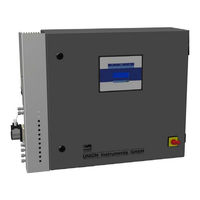
Table of Contents
Attention
7
Table of Contents
7
1 EC Declaration of Conformity
9
2 Safety Notes
11
Warnings and Symbols
11
Fundamentals of Proper Use
12
Personnel and Qualifications
12
Safety Notes
13
General Notes on Safety
13
Notes Regarding Special Hazards
13
Regular Operator Training
13
Workplace Hazard Analysis
14
3 Safety Equipment
15
Main Switch
15
Door - Not Electronically Queried
15
Ventilator Monitoring
15
Abb. 3.1: Main Switch (Exemplarisch)
15
Markings and Warnings
16
Fig. 3.2: Markings and Warnings
16
Fig. 3.3: Warning in Housing
16
4 Connections
17
Connection of Process Gas and Electric Ball Valve
18
Fig. 4.2: Connection of Process Gas and Electric Ball Valve
18
Accessories
19
5 Transport, Setup and Acceptance
21
Transport
21
Ambient Conditions
22
Storage Conditions
22
Set up and Connection
22
Setup Site
22
Wall Attachment
23
Fig. 5.1: Wall Attachment
23
Process Gas
24
Electrical Connection
25
Electrical Interfaces
25
Fig. 5.2: Power Supply X2 with Fuses
26
Fig. 5.3: Electrical Interfaces
27
Fig. 5.4: Relay X10A, Outputs K1 - K3
28
Fig. 5.5: Relay X10A Terminal Assignment
28
Fig. 5.6: Analogue Outputs X11A, Connections
29
Fig. 5.7: Remote Control Unit RCM X15
30
Fig. 5.8: Relay X13A, Connections Ball Valves
31
Operator Safety Precautions
32
Startup after Setup
32
Documentation
32
6 Startup /Switching on
33
7 Description of the Workplaces/Operating Elements
35
Workplaces
35
Fig. 7.1: Workplaces
35
8 Operation
37
Description of Display
38
Using the Membrane Keypad
38
Fig. 8.1: Operating Elements
38
Displayarea
39
Available Displays
39
Fig. 8.2: Display Area
39
Menu Structure
40
Navigate with the Arrow Keys Left
41
Dqg Uljkw
41
Navigation with Arrow Keys up DQG GRZQ
42
Navigation with ESC and MENU
43
Measurement Display
44
Measuring Channel Display
44
Saved Measured Values
45
Display in the Warmup Phase
45
Select Language
46
Password
47
9 Decommissioning/Switching off
49
10 Maintenance
51
Preparations
51
Maintenance Work/Inspection
52
11 Troubleshooting
55
Preparations
55
Changing/Replacing Fuses
56
Messages/Malfunctions on the Display
56
Display of Messages/Malfunctions
56
Visualizing the Error List
56
Troubleshooting List
56
12 Service
57
13 Associated Documents
59
14 Disposal
61
15 Spare Parts
63
16 Annex
64
Index
64
Table of Figures
65
Advertisement
Related Products
Union Instruments INCA 4000
Union Instruments INCA4000
Union Instruments INCA5051
Union Instruments INCA6001
Union Instruments INCA5021
Union Instruments INCA6003
Union Instruments INCA6004
Union Instruments INCA5011
Union Instruments INCA Series
Union Instruments INCA 3000
Union Instruments Categories
Measuring Instruments
Accessories
Control Systems
More Union Instruments Manuals
Login
Sign In
OR
Sign in with Facebook
Sign in with Google
Upload manual
Upload from disk
Upload from URL