Sign In
Upload
Manuals
Brands
Unex Manuals
Network Hardware
OBU-301E
Unex OBU-301E Manuals
Manuals and User Guides for Unex OBU-301E. We have
1
Unex OBU-301E manual available for free PDF download: Quick Start Manual
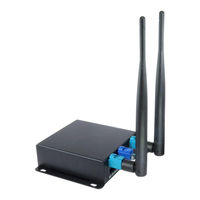
Unex OBU-301E Quick Start Manual (27 pages)
Brand:
Unex
| Category:
Network Hardware
| Size: 2.22 MB
Table of Contents
Table of Contents
2
Objective
5
Reference
5
Limited Warranty Policy
5
Safety Guidelines
6
Product Appearance
6
Figure 1: OBU-301(V2)/Obu-351 Series Package Content
7
Figure 2: EVK-301(V2)/Evk-351 Series Package Content
7
Functional Block Diagram
8
Figure 3: OBU-301(V2)/Obu-351 Series Complete Assembly Appearance
8
Figure 4: Functional Block Diagram
8
Electrical Characteristics
9
Absolute Maximum Ratings
9
Recommended Operating Conditions
9
Table 1. Absolute Maximum Ratings
9
Table 2. Recommended Operating Conditions
9
Power Consumption
11
I/O Interfaces
11
OBU-301(V2)/Obu-351
11
External Interfaces
11
Figure 5: LED
11
Table 3: Power Consumption
11
Figure 6: USB0 (CN2)
12
Table 4: LED Function
12
Table 5: USB0 (CN2) Pinout
12
Figure 7: Ethernet Port
13
Figure 8: I/O Port (J8)
13
Table 6: Ethernet LED Function
13
Figure 9: I/O Port Cable Connector
14
Table 7: I/O Port Pin Map (J8)
14
Table 8: I/O Port Pinout (J8)
14
Internal Interfaces
15
Figure 10: V2X Antenna Ports
15
Figure 11: GNSS Antenna Port
15
Figure 12: Mini Pcie Port (J6)
16
Table 9: Mini Pcie Pinout (J6, Row 0)
16
Table 10: Mini Pcie Pinout (J6, Row 1)
16
Figure 13: SIM Slot (J7)
17
Figure 14: Tamper Input (J5)
18
Table 11: Tamper Functions (J5)
18
Figure 15: SAR ADC Input (J4)
19
Table 12: SAR ADC Functions
19
Table 13: SAR ADC Performance
19
I/O Conversion Board (EVK-351 Series Only)
20
Figure 16: DIP Switches. SW3 (Left), SW2 (Right)
20
Table 14: SW2 and SW3 Functions
20
Console
21
Ext GNSS
21
Figure 17: EX-46 (Left), EX-47 (Right)
21
Figure 18: Console Port (CN4)
21
Figure 19: Ext GNSS Port (CN6)
21
Table 15: Console Pinout (CN4)
21
Can0
22
Figure 20: CAN0 Port (CN5)
22
Table 16: Ext GNSS Pinout (CN6)
22
Table 17: CAN0 Pinout (CN5)
22
Can1
23
Figure 21: CAN0 Terminator Jumpers (JP1/JP2)
23
Figure 22: CAN1 Port (CN7)
23
Figure 23: CAN1 Terminator Jumpers (JP3/JP4)
23
Table 18: CAN1 Pinout (CN7)
23
Usb1
24
Gpio
24
Figure 24: USB1 Port (CN2)
24
Figure 25: GPIO Headers (J1)
24
Table 19: USB1 Pinout (CN2)
24
Table 20: GPIO Pinout (J1)
24
DC Power Jack
25
Reset Button
25
Figure 26: DC Power Jack
25
Figure 27: Reset Button
25
Dimensions and Weight
26
Figure 28: Mechanical Dimensions - TOP
26
Figure 29: Mechanical Dimensions - FRONT
26
Table 21: Dimensions and Weight
26
Software Settings
27
Table 22: Unex BSP Interface Settings
27
Advertisement
Advertisement
Related Products
Unex OBU-300
Unex OBU-301U
Unex OBU-351
Unex OBU-351E
Unex OBU-351U
Unex OBU-352 Series
Unex OBU-352ED
Unex OBU-352UC
Unex OBU-352UD
Unex OBU-352EC
Unex Categories
Lighting Equipment
Outdoor Light
Control Unit
Network Hardware
Racks & Stands
More Unex Manuals
Login
Sign In
OR
Sign in with Facebook
Sign in with Google
Upload manual
Upload from disk
Upload from URL