Sign In
Upload
Manuals
Brands
Tyco Fire Protection Products Manuals
Fire Extinguisher
FAST2000/2
Tyco Fire Protection Products FAST2000/2 Manuals
Manuals and User Guides for Tyco Fire Protection Products FAST2000/2. We have
1
Tyco Fire Protection Products FAST2000/2 manual available for free PDF download: Installation Instructions Manual
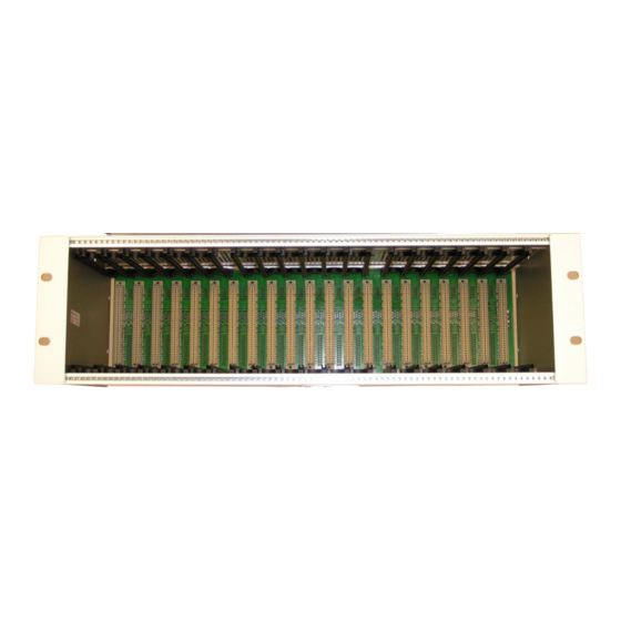
Tyco Fire Protection Products FAST2000/2 Installation Instructions Manual (128 pages)
19”-Rack Version Fire Detection and Extinguishing Control System
Brand:
Tyco Fire Protection Products
| Category:
Fire Extinguisher
| Size: 10 MB
Table of Contents
Table of Contents
2
Introduction
8
Safety
8
A few Do's and Don'ts
8
Warranties and Constraints
8
2 Description and Structure
9
Mechanical Structure
9
19" Rack
9
Electrical Connections
10
Power Supply
11
Detection Loops
11
System Sensor Loop Devices
12
Tyco Loop Devices
13
Brief Description of Detection Circuit Operation
14
Scanning the Detection Loops
14
Downloading Type Information to the LM-Module
15
Scan Time Calculation
15
Extinguishing
15
Extinguishing Conditions
16
Extinguishing-Stop (Emergency Hold)
16
3 The Modules of the FAST2000 /2
17
CM-32/2 Control Module
18
Circuit Description
20
Electrical Connections
21
Jumper Settings
21
Technical Data
22
CM-32T Power Supply Supervisory Module
22
Circuit Description
23
Pin - Configuration
23
Fuse Information
23
Electrical and Mechanical Data
23
CM-32T/2 Power Supply Supervisory Module (Since 2013)
24
Circuit Description
24
DIP Switch S1
25
LED- Indications
25
Klemmenbelegung
25
Fuse Information
26
Technical Data
26
CM-32F Fire Brigade Termination Board (until 2008)
26
Circuit Description
26
Fuse Information
27
Technical Data
27
CM-32F/2 Fire Brigade Termination Board (Since2009)
27
Circuit Description
28
Fuse Information
28
Technical Data
28
CM-32R Common Relay Termination Board
29
Circuit Description
29
Electrical Connections
29
Technical Data
30
CM-32P RS232 Interface Card for Printer Connection
30
Power Converter Module
30
Inputs and Outputs
31
Electrical Connections
31
Technical Data
32
DM-32/2 Display Module
32
Electrical Connections
32
Technical Data
33
Power Supply Unit ADC 5483
33
LM-32TX Loop-Module Extinguishing for
33
Setting of Module Address
34
Circuit Description
34
Electrical Connections
35
64-Pin Edge Connector Pin-Out
35
Electrical and Mechanical Data
36
LM-32TXT Extinguishing Area Termination Board for Tyco Loop Devices
36
Electrical Connections
37
LED Indications
40
Fuse Information
40
Electrical and Mechanical Data
41
LM-32D Loop Module Detection
41
Setting the Card-Address
41
Circuit Description
42
Electrical Connections
42
64-Pin Edge Connector Pin-Out
43
Electrical and Mechanical Data
43
LM-32DT Detection Area Termination Board
43
Electrical Connections
44
Fuse Information
46
Electrical and Mechanical Data
46
LM-32E Loop Module Extinguishing
47
Setting the Card-Address
47
Circuit Description
47
64-Pin Edge Connector Pin-Out
48
Electrical and Mechanical Data
48
LM-32ET Extinguishing Area Termination Board
49
Electrical Connections
49
Fuse Information
53
Electrical and Mechanical Data
53
LM-32SCT Ext. Area Termination Board with Stepper Motor Output
53
Electrical Connections
53
Fuse Information
57
Electrical and Mechanical Data
57
Alarm Monitoring for Stepper Motor Systems
57
Extinguishing Module
57
EM-32T Extinguishing Module Termination Board I
58
EM-32TER Extinguishing Module Termination Board II
59
EM-32SCT Ext. Module Termination Board III with Stepper Motor Output
60
Input/Output Module
61
Inputs and Outputs
61
Circuit Description
61
User Set-Up
61
Electrical Connections
62
Electrical and Mechanical Data
63
IO-32T Output Termination Board
63
Circuit Description
63
Electrical Connections
63
Corresponding Set-Up´s IO-32T
64
Ribbon Cable Connectors J1 and J2
64
Terminal Block Connections
64
Electrical and Mechanical Data
64
IO-32TOC Input/Output Termination Board Open Collector
65
Terminal Block Connections
65
Zone Indication Module
66
Revision Module
66
Communication Termination Board, CM-32CTCB2
66
Electrical Connections
66
Jumper Settings
67
Technical Data
68
CM-32CTCM422 RS422 Termination Board
68
Electrical Connections
69
Driver Module Connector J1
69
RS422/RS485 Terminal Block J2
69
Led's
69
Jumper Settings
69
Technical Data
71
CM-32CTCM232 RS232 Termination Board
71
Electrical Connections
71
Driver Module Connector J1
71
RS232 Terminal Block J2
72
RS232 Ribbon Cable Connector J3
72
Led's
73
Jumper Settings
73
Technical Data
73
CM-32CTCM1 30Ma Termination Board
73
Electrical Connections
74
Driver Module Connector J1
74
30Ma Terminal Block J2
74
Led's
74
Jumper Settings
74
Technical Data
75
CM-32CTOPT1 Fibre Optic Termination Board
75
Electrical/Optical Connections
75
Driver Module Connector J1
76
Fibre Optic Connectors U1-U2
76
Led's
76
Jumper Settings
76
Technical Data
76
4 Installation
78
General
78
Mechanical Installation
78
Electrical Installation
78
Power and Battery Supply
78
Detection Circuits
79
Auxiliary Inputs
79
Sounder Outputs
80
Dedicated Relays
80
Relay Connections
81
Valve Outputs
81
Fire Brigade-Interface
81
Printer and RS-232 Interface
82
5 Commissioning
83
Detection Loops
83
Outputs
83
Inputs
83
Record Keeping
83
Power up
84
The Charger
84
The Battery
84
Commissioning of the Loops
85
Wiring Checks
85
Electrical Checks
86
Connecting the Sounder Outputs
86
Connecting the Dedicated Control-Relays
87
Connecting the Fault Output
88
Zone Valve Output
88
Connecting the Control-Relay Outputs
88
Dedicated Auxiliary Inputs
88
Fire-Brigade Panel
89
Interface and Printer Connection
89
System Initiating
89
Complete System Test
90
6 Fault Finding
92
Automatic Monitoring
92
False Alarm Reduction
92
Fault Alarms
92
System Data
92
Trouble Shooting
92
The Display-Module DM-32 Is „Dead
93
The Control-Module CM-32 Is „Dead
94
Power Supply Failure
94
Open Circuit on the Alarm Bell Circuit
95
Short Circuit on the Alarm Bell Circuit
95
Open Circuit on Detection Loops
96
Short Circuit on Detection Loop
96
Earth Fault
97
7 Service and Maintenance
98
Maintenance Program
98
The Main Service
98
Main Service of the Man/Machine Interface
98
Visual Inspection of the Panel
98
Main Service of the Power Supply
98
Checking the Communication Bus
99
Main Service of the Detection Loops
99
Main Service of Sounder Loops
100
Checking the Control-Relays
100
Checking the Serial Interface
100
Checking the Auxiliary Inputs
100
Checking the Fire Brigade Panel
100
The Minor Service
100
Minor Service of the Man/Machine Interface
101
Minor Service of the Power Supply
101
Minor Service of the Detection Loops
101
Minor Service of the Sounder Circuits
101
Checking the Calling Equipment
102
8 Appendix A: the Default Program
103
Fault Alarm Inputs
103
Fire Alarm Inputs
103
Prewarnings
103
General Auxiliary Inputs
103
9 Signals on 64-Pin Connector
104
Signals on Connector of CM-32
104
Signals on Connector of EM-32
104
Signals on Connector of LM-32
105
Signals on Connector of IO-32
107
10 Address Setting with DIP-Switches on LM- and EM-Module
108
11 Service Functions
110
12 Wire Resistance Considerations
111
13 Analogue Values
113
14 Ordering the Dummy Plates
114
15 FAST2000 Loop Loading and Battery Calculations
115
Introduction
115
Short-Circuit Isolators
115
Loop Loading
115
LPS800 Loop Powered Sounder Module Loop Loading Considerations
119
Cable Type and Cable Length
120
General
120
Cable Types
120
Cable Length
120
Cable Screen
121
Voltage Drop
121
Calculation Sheets
121
Loop Loading Calculation Sheet Per Loop
122
Loading between Line Isolators Calculation Sheet
125
16 MZX-Melder, Störungscodes
126
17 Revision History
128
Advertisement
Advertisement
Related Products
Tyco Fire Protection Products F3200
Tyco Fire Protection Products Categories
Firefighting Equipment
Irrigation System
Fire Extinguisher
Control Panel
Fire Alarms
More Tyco Fire Protection Products Manuals
Login
Sign In
OR
Sign in with Facebook
Sign in with Google
Upload manual
Upload from disk
Upload from URL