
Summary of Contents for Tyco Fire Protection Products FAST2000/2
- Page 1 INSTALLATION INSTRUCTIONS ® FAST2000 19”-Rack Version Fire Detection and Extinguishing Control System Version 4.10 TSM/Kli 05.03.2017 © Copyright tyco Fire Protection Products Doc: 3-052-011d...
-
Page 2: Table Of Contents
CM-32F/2 Fire Brigade Termination Board (since2009) ............. 26 3.5.1 Circuit Description ......................27 3.5.2 Fuse information ....................... 27 3.5.3 Technical Data ........................27 CM-32R Common Relay Termination Board ..............28 Seite: 1 Version 4.10 TSM/Kli 05.03.2017 Copyright tyco Fire Protection Products Doc: 3-052-011d... - Page 3 3.17.1 Electrical Connections ...................... 52 3.17.2 Fuse Information ....................... 56 3.17.3 Electrical and mechanical Data ..................56 3.18 AM-32 Alarm Monitoring for Stepper Motor Systems............56 Seite: 2 Version 4.10 TSM/Kli 05.03.2017 Copyright tyco Fire Protection Products Doc: 3-052-011d...
- Page 4 3.31.2 Driver module connector J1 ....................73 3.31.3 30mA terminal block J2..................... 73 3.31.4 LED's ..........................73 3.31.5 JUMPER SETTINGS ......................73 3.31.6 TECHNICAL DATA ......................74 Seite: 3 Version 4.10 TSM/Kli 05.03.2017 Copyright tyco Fire Protection Products Doc: 3-052-011d...
- Page 5 Fault Finding .......................... 91 Automatic Monitoring ......................91 6.1.1 False Alarm Reduction...................... 91 6.1.2 Fault Alarms ........................91 System Data ........................91 6.2.1 Trouble Shooting ....................... 91 Seite: 4 Version 4.10 TSM/Kli 05.03.2017 Copyright tyco Fire Protection Products Doc: 3-052-011d...
- Page 6 FAST2000 Loop Loading and Battery Calculations ............. 114 15.1 Introduction ........................114 15.2 Short-circuit isolators ......................114 15.3 Loop loading ........................114 15.4 LPS800 loop powered sounder module loop loading considerations ....... 118 Seite: 5 Version 4.10 TSM/Kli 05.03.2017 Copyright tyco Fire Protection Products Doc: 3-052-011d...
- Page 7 15.7.1 Loop Loading Calculation Sheet Per Loop ..............121 15.7.2 Loading Between Line Isolators Calculation Sheet ............124 MZX-Melder, Störungscodes ....................125 Revision History ........................127 Seite: 6 Version 4.10 TSM/Kli 05.03.2017 Copyright tyco Fire Protection Products Doc: 3-052-011d...
-
Page 8: Introduction
Warranties and Constraints Please note that repairs or modifications to the equipment without the prior written consent from Tyco Safety Products invalidate the warranty. Seite: 7 Version 4.10 TSM/Kli 05.03.2017 Copyright tyco Fire Protection Products Doc: 3-052-011d... -
Page 9: Description And Structure
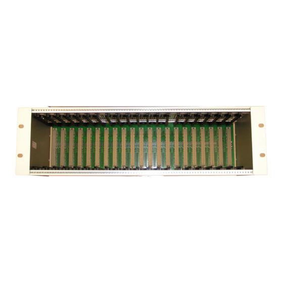
(see 2.2, electrical connections). The following figure shows a possible arrangement of the modules in the first 19”-rack. Figure 1: 19” Rack with Modules Seite: 8 Version 4.10 TSM/Kli 05.03.2017 Copyright tyco Fire Protection Products Doc: 3-052-011d... -
Page 10: Electrical Connections
CM-32 uses the 10 pin connector for RS-232 communication (connection to CM-32P). The 10-pin connector is not used with the EM-32 module. Figure 2: 19” Racks with Modules, Front View Seite: 9 Version 4.10 TSM/Kli 05.03.2017 Copyright tyco Fire Protection Products Doc: 3-052-011d... -
Page 11: Power Supply
System Sensor loop devices of series 200 and 500 are used. Automatic fire detectors (analogue sensors) and a range of input and output modules are available from both series. Seite: 10 Version 4.10 TSM/Kli 05.03.2017 Copyright tyco Fire Protection Products Doc: 3-052-011d... -
Page 12: System Sensor Loop Devices
Control module M201E-240DIN (one output rated for 240V, DIN rail version) • Short circuit isolator M200XE • Short circuit isolator AX91IS (obsolete) • Isolator base B524IEFT • Manual call point (red) HFM/3/22/17/ (obsolete) and HFM/3/25/17/ • Seite: 11 Version 4.10 TSM/Kli 05.03.2017 Copyright tyco Fire Protection Products Doc: 3-052-011d... -
Page 13: Tyco Loop Devices
Input-/Output Module SIO800 (one input, one output) • Multi-Input-/Output Module MIO800 • Relay Output Module RIM800 • Short Circuit Isolator LIM800 • Manual Call Point (rot) KAC CP820 • Seite: 12 Version 4.10 TSM/Kli 05.03.2017 Copyright tyco Fire Protection Products Doc: 3-052-011d... -
Page 14: Brief Description Of Detection Circuit Operation
30 ms. Note, however, that a single scan can never take less than one second. So if the maximum number of devices on any of the Seite: 13 Version 4.10 TSM/Kli 05.03.2017 Copyright tyco Fire Protection Products Doc: 3-052-011d... -
Page 15: Downloading Type Information To The Lm-Module
From this it follows that the maximum response time to a fire situation is 6.1 seconds. Extinguishing ® The FAST2000 has seven modules that are dedicated for extinguishing systems. The cards are; LM- 32E, LM-32ET, LM-32SCT, EM-32, EM-32T, EM-32TER and EM-32STE. Seite: 14 Version 4.10 TSM/Kli 05.03.2017 Copyright tyco Fire Protection Products Doc: 3-052-011d... -
Page 16: Extinguishing Conditions
!! A fault of input 5 must be cleared immediately !! !! The fire protection system is disabled !! For further technical information on the various inputs and outputs see chapter 3 and 4. Seite: 15 Version 4.10 TSM/Kli 05.03.2017 Copyright tyco Fire Protection Products Doc: 3-052-011d... -
Page 17: The Modules Of The Fast2000 /2
/2 is designed for a specific task within the whole system. Some of the components are independent "intelligent" units (with processor), whereas others are passive units, which are controlled by an "intelligent" module. Seite: 16 Version 4.10 TSM/Kli 05.03.2017 Copyright tyco Fire Protection Products Doc: 3-052-011d... -
Page 18: Cm-32/2 Control Module
This means that the panel has probably not been able to transmit the fire alarm message to the fire brigade. It is therefore essential that the fire brigade is called manually as soon as this indicator lights. Seite: 17 Version 4.10 TSM/Kli 05.03.2017 Copyright tyco Fire Protection Products Doc: 3-052-011d... - Page 19 'Fire'. Additionally it provides a 24V supervised and normally active 'Fault' output. 4. CM-32P - Provides two RS-232 communication channels for printer, PC, etc. 5. CM-32CTCB2 - Provides up-to two communication channels Seite: 18 Version 4.10 TSM/Kli 05.03.2017 Copyright tyco Fire Protection Products Doc: 3-052-011d...
-
Page 20: Circuit Description
The PIB-32 board (LED board) connected to the CM-32 is of the wide type with 10 different colour LED indicators. The purpose and colour of the LED's are: LED no. State LED Colour Fire Test Yellow Isolated Yellow Fault Yellow System Fault Yellow Seite: 19 Version 4.10 TSM/Kli 05.03.2017 Copyright tyco Fire Protection Products Doc: 3-052-011d... -
Page 21: Electrical Connections
Jumper blocks JP6 and JP7 are used to select serial channel C as multi drop for rack mode, or as separate RX / TX for standalone mode. Seite: 20 Version 4.10 TSM/Kli 05.03.2017 Copyright tyco Fire Protection Products Doc: 3-052-011d... -
Page 22: Technical Data
Important: From this time onwards, the entire fire protection installation, including the extinguishing system, is no longer in operation. Other suitable fire protection precautions must be set up immediately. Seite: 21 Version 4.10 TSM/Kli 05.03.2017 Copyright tyco Fire Protection Products Doc: 3-052-011d... -
Page 23: Circuit Description
Electrical and mechanical Data Voltage output range: 19 ... 30 V Shutdown buzzer active: 10 ... 19 V Current consumption, normal: 20 mA PCB dimensions (mm): 145 x 72 Seite: 22 Version 4.10 TSM/Kli 05.03.2017 Copyright tyco Fire Protection Products Doc: 3-052-011d... -
Page 24: Cm-32T/2 Power Supply Supervisory Module (Since 2013)
A short circuit on the charger will cause the fuse to blow, and the system will be supplied by the battery. Seite: 23 Version 4.10 TSM/Kli 05.03.2017 Copyright tyco Fire Protection Products Doc: 3-052-011d... -
Page 25: Dip Switch S1
+ 24V Out II Mains fault - 24V Out II Battery fault + Battery connection Earth fault - Battery connection + 24V Supply - 24V Supply Earth Seite: 24 Version 4.10 TSM/Kli 05.03.2017 Copyright tyco Fire Protection Products Doc: 3-052-011d... -
Page 26: Fuse Information
Fire Brigade call isolated Input Capacitor protection Input resistance > 10 kΩ Fire Brigade call feedback Input Fire Brigade call test Input Pin # Description In-/Output Special features Seite: 25 Version 4.10 TSM/Kli 05.03.2017 Copyright tyco Fire Protection Products Doc: 3-052-011d... -
Page 27: Fuse Information
LED’s for indication of the various states and receive the signals from the fire brigade panel. It is connected to the 26- core flat cable connection of the CM-module. Seite: 26 Version 4.10 TSM/Kli 05.03.2017 Copyright tyco Fire Protection Products Doc: 3-052-011d... -
Page 28: Circuit Description
Max. current fire brigade call output: UE monitoring range: 50 Ω - 1000 Ω UE line resistance: max. 15 Ω Length: 110 mm Width: 72 mm Seite: 27 Version 4.10 TSM/Kli 05.03.2017 Copyright tyco Fire Protection Products Doc: 3-052-011d... -
Page 29: Cm-32R Common Relay Termination Board
26 pin ribbon cable connector: J1 Pin # Brief description Activated, output Released, output CO2-Stop Fire, output Fault, output Fault supervising input 0V from back plane 0V from back plane Seite: 28 Version 4.10 TSM/Kli 05.03.2017 Copyright tyco Fire Protection Products Doc: 3-052-011d... -
Page 30: Technical Data
Option 1 - The PM-32 can be able to indicate the total loss of the power supply, specified by the EN54-2 as an option with requirements. This option is not available as a standard. Seite: 29 Version 4.10 TSM/Kli 05.03.2017 Copyright tyco Fire Protection Products Doc: 3-052-011d... -
Page 31: Inputs And Outputs
Intercard +8 V DC connection 2. The two pins header for connection of a 9V external power source is optional and not mounted as a standard. Seite: 30 Version 4.10 TSM/Kli 05.03.2017 Copyright tyco Fire Protection Products Doc: 3-052-011d... -
Page 32: Technical Data
J6 - The second of the two 22 pin female headers used to connect to the FAST2000 Compact PIB. • J7 - The 11 pin header used for connecting the keyboard foil in FAST2000 rack configuration. External buzzer terminal block J3 (optional) Seite: 31 Version 4.10 TSM/Kli 05.03.2017 Copyright tyco Fire Protection Products Doc: 3-052-011d... -
Page 33: Technical Data
Funktionen des entsprechenden Löschbereiches. Das LM-32TX verfügt über eine serielle Schnittstelle zur Ansteuerung von 2 IO-32 Baugruppen, und stellt damit bis zu 48 zusätzliche Ausgänge zur Verfügung, die mit Relaiskarten oder als Open-Collector beschaltet sein können. Seite: 32 Version 4.10 TSM/Kli 05.03.2017 Copyright tyco Fire Protection Products Doc: 3-052-011d... -
Page 34: Setting Of Module Address
DC-DC converters, one for each loop. The block diagram below shows the basic design of the LM-32TX, and the interconnection both internally and externally to other units in the Fast2000 system. Seite: 33 Version 4.10 TSM/Kli 05.03.2017 Copyright tyco Fire Protection Products Doc: 3-052-011d... -
Page 35: Electrical Connections
3.11.4 64-pin Edge Connector Pin-out The signals on the LM-32D 64 pin euro connector and the two backplane headers are described in chapter 9. Seite: 34 Version 4.10 TSM/Kli 05.03.2017 Copyright tyco Fire Protection Products Doc: 3-052-011d... -
Page 36: Electrical And Mechanical Data
19” rack. Connection is by means of ribbon cables from 10 and 26-core connector on the LM-32TXT to the respective connectors on the rear side of the 19” rack. Seite: 35 Version 4.10 TSM/Kli 05.03.2017 Copyright tyco Fire Protection Products Doc: 3-052-011d... -
Page 37: Electrical Connections
Activating one input will be associated with one common panel indication. Inspection of the switches will show which input (s) is set by activated LED on the switch housing. Seite: 36 Version 4.10 TSM/Kli 05.03.2017 Copyright tyco Fire Protection Products Doc: 3-052-011d... - Page 38 The connection points for the sounder outputs are as listed in table below: Terminal Output Polarity Bell circuit number number number Seite: 37 Version 4.10 TSM/Kli 05.03.2017 Copyright tyco Fire Protection Products Doc: 3-052-011d...
- Page 39 The pin description of the 10- and 26-pin connector is listed in the tables below. 10pin Ribbon cable, loops Pin# Loop# Polarity Description Output Return Output Return Seite: 38 Version 4.10 TSM/Kli 05.03.2017 Copyright tyco Fire Protection Products Doc: 3-052-011d...
-
Page 40: Led Indications
3.12.3 Fuse Information Ref. Fuse marking Fuse data 2A/32V Sounder output 1 MINI Fuse Fast-Acting Type Littlefuse 0297002 2A/32V Sounder output 2 MINI Fuse Fast-Acting Type Littlefuse 0297002 Seite: 39 Version 4.10 TSM/Kli 05.03.2017 Copyright tyco Fire Protection Products Doc: 3-052-011d... -
Page 41: Electrical And Mechanical Data
This address must be in the range 1 to 250 and is set by using an eight position DIP switch. For further information about adjusting the DIP-switch, refer to appendix B. Seite: 40 Version 4.10 TSM/Kli 05.03.2017 Copyright tyco Fire Protection Products Doc: 3-052-011d... -
Page 42: Circuit Description
FAST2000 system is routed through the this connector. The PCB also has two connection points for connecting the LED indication board. Seite: 41 Version 4.10 TSM/Kli 05.03.2017 Copyright tyco Fire Protection Products Doc: 3-052-011d... -
Page 43: 64-Pin Edge Connector Pin-Out
10 pin and the 26 pin header connectors on the LM-32DT and the equivalent pins on the LM-32D. The connection point for the LM-32D is on the backplane of the 19" rack where the LM-32D is located. Seite: 42 Version 4.10 TSM/Kli 05.03.2017 Copyright tyco Fire Protection Products Doc: 3-052-011d... -
Page 44: Electrical Connections
Inspection of the switches will show which input (s) is set by activated LED on the switch housing. Maximum 7 input switches may be connected to the same input. If more Seite: 43 Version 4.10 TSM/Kli 05.03.2017 Copyright tyco Fire Protection Products Doc: 3-052-011d... - Page 45 + and -. If needed one of the 24V connections can be used as an 24V feed through output. The LM-32DT must have a 24V supply connection in order to be in normal operation. Seite: 44 Version 4.10 TSM/Kli 05.03.2017 Copyright tyco Fire Protection Products Doc: 3-052-011d...
-
Page 46: Fuse Information
Nominal Output voltage: 27,6 V DC Nominal operating voltage: Output circuits: 24 V DC Logic circuitry: 8 V DC PCB current consumption: 50 mA PCB dimensions (mm): 72x132 Seite: 45 Version 4.10 TSM/Kli 05.03.2017 Copyright tyco Fire Protection Products Doc: 3-052-011d... -
Page 47: Lm-32E Loop Module Extinguishing
The block diagram below attempts to show the basic design of the LM-32E and how it is connected to the other modules and equipment it interacts with. Seite: 46 Version 4.10 TSM/Kli 05.03.2017 Copyright tyco Fire Protection Products Doc: 3-052-011d... -
Page 48: 64-Pin Edge Connector Pin-Out
8,0 ... 9,0 V DC Current consumption at 8V: 60 mA Note: The specified current consumption does not include other modules and cards connected to the LM-32E. Seite: 47 Version 4.10 TSM/Kli 05.03.2017 Copyright tyco Fire Protection Products Doc: 3-052-011d... -
Page 49: Lm-32Et Extinguishing Area Termination Board
Detection loop 1 has LOW end connection to terminals 1 and 2, where 1 is the positive terminal and 2 is the negative terminal. The 'LOW' terminals are normally used for connection of the Seite: 48 Version 4.10 TSM/Kli 05.03.2017 Copyright tyco Fire Protection Products Doc: 3-052-011d... - Page 50 Positive terminal Extinguishing system blocked input Negative terminal Zone not closed Positive terminal Zone not closed Negative terminal Released input Positive terminal Released input Negative terminal Seite: 49 Version 4.10 TSM/Kli 05.03.2017 Copyright tyco Fire Protection Products Doc: 3-052-011d...
- Page 51 The connection points for the valve outputs are as listed in the table below: Terminal Valve Terminal polarity Zone valve Positive terminal Zone valve Negative terminal stop valve Positive terminal stop valve Negative terminal Seite: 50 Version 4.10 TSM/Kli 05.03.2017 Copyright tyco Fire Protection Products Doc: 3-052-011d...
- Page 52 Brief Description of 10pin Connector Loop 1, Positive connection, low end Loop 1, Negative connection, low end Loop 1, Positive connection, high end Loop 1, Negative connection, high end Seite: 51 Version 4.10 TSM/Kli 05.03.2017 Copyright tyco Fire Protection Products Doc: 3-052-011d...
-
Page 53: Fuse Information
It is recommended that the overall resistance of both wires in the detection circuitry are checked before any short circuit isolators are fitted. Seite: 52 Version 4.10 TSM/Kli 05.03.2017 Copyright tyco Fire Protection Products Doc: 3-052-011d... - Page 54 Terminal Input Terminal polarity Manual release input Positive terminal Manual release input Negative terminal Extinguishing system blocked input Positive terminal Extinguishing system blocked input Negative terminal Seite: 53 Version 4.10 TSM/Kli 05.03.2017 Copyright tyco Fire Protection Products Doc: 3-052-011d...
- Page 55 Inductance below 11,5 ohms is seen as a short circuit. For inductance above 700 ohms it is seen as a open circuit. The connection points for the valve outputs are as listed in the table below: Seite: 54 Version 4.10 TSM/Kli 05.03.2017 Copyright tyco Fire Protection Products Doc: 3-052-011d...
- Page 56 Blocked zone V input Zone valve open / Zone blocking valve not open Released input Hold off input Second shot input 0V from backplane 0V from backplane Seite: 55 Version 4.10 TSM/Kli 05.03.2017 Copyright tyco Fire Protection Products Doc: 3-052-011d...
-
Page 57: Fuse Information
EM-32 the module provides two outputs (main and reserve) for the fire extinguishing agent or only one (main) and 6 inputs with pre-programmed functions. The alarm Seite: 56 Version 4.10 TSM/Kli 05.03.2017 Copyright tyco Fire Protection Products Doc: 3-052-011d... -
Page 58: Em-32T Extinguishing Module Termination Board I
This is an input for supervising the mechanical position of the mechanical time delay device. The indication is shown at the display. Input 6 • not pre-programmed (for future use) Seite: 57 Version 4.10 TSM/Kli 05.03.2017 Copyright tyco Fire Protection Products Doc: 3-052-011d... -
Page 59: Em-32Ter Extinguishing Module Termination Board Ii
Input 6 • not pre-programmed (for future use) Input 7 • not pre-programmed (for future use) • Input 8 not pre-programmed (for future use) Seite: 58 Version 4.10 TSM/Kli 05.03.2017 Copyright tyco Fire Protection Products Doc: 3-052-011d... -
Page 60: Em-32Sct Ext. Module Termination Board Iii With Stepper Motor Output
• Input 6 not pre-programmed (for future use) Input 7 • not pre-programmed (for future use) Input 8 • not pre-programmed (for future use) Seite: 59 Version 4.10 TSM/Kli 05.03.2017 Copyright tyco Fire Protection Products Doc: 3-052-011d... -
Page 61: Input/Output Module
The IO-32 card is controlled by a LM-32D/E or CM-32 module which is usually plugged into one of the neighbouring slots. The necessary control lines must then be patched through by fitting the appropriate straps on the back plane. Seite: 60 Version 4.10 TSM/Kli 05.03.2017 Copyright tyco Fire Protection Products Doc: 3-052-011d... -
Page 62: Electrical Connections
Input/Output line 21 Input/Output line 9 Input/Output line 22 Input/Output line 10 Input/Output line 23 Input/Output line 11 Input/Output line 24 Input/Output line 12 0V from backplane Seite: 61 Version 4.10 TSM/Kli 05.03.2017 Copyright tyco Fire Protection Products Doc: 3-052-011d... -
Page 63: Electrical And Mechanical Data
This means that any control voltage that the relays should switch must be supplied through terminal C. Seite: 62 Version 4.10 TSM/Kli 05.03.2017 Copyright tyco Fire Protection Products Doc: 3-052-011d... -
Page 64: Corresponding Set-Up´s Io-32T
Relay 4 common Earth Relay 5 normally closed +24V DC Relay 5 normally open Relay 5 common 3.24.6 Electrical and mechanical Data Supply voltage range: 19 ... 30V Seite: 63 Version 4.10 TSM/Kli 05.03.2017 Copyright tyco Fire Protection Products Doc: 3-052-011d... -
Page 65: Io-32Toc Input/Output Termination Board Open Collector
Output 18 Output 7 Output 19 Output 8 Output 20 Output 9 Output 21 Output 10 Output 22 Output 11 Output 23 Output 12 Output 24 Seite: 64 Version 4.10 TSM/Kli 05.03.2017 Copyright tyco Fire Protection Products Doc: 3-052-011d... -
Page 66: Zone Indication Module
When connected to the FAST2000-/2 through ribbon cable, 24V supply only has to be connected to 24V terminals I. The earth connection is capacitively connected to 0V and +24V to reduce interference. For more details on jumper settings see section 3.24.7. Seite: 65 Version 4.10 TSM/Kli 05.03.2017 Copyright tyco Fire Protection Products Doc: 3-052-011d... -
Page 67: Jumper Settings
RTS C and CTS C are enabled / disabled by jumpers LK2 and LK3 For details on jumper settings see section 3.25.2. For details on driver modules see sections 3.26 to 3.30. 3.28.2 JUMPER SETTINGS Jumper block LK1: Seite: 66 Version 4.10 TSM/Kli 05.03.2017 Copyright tyco Fire Protection Products Doc: 3-052-011d... -
Page 68: Technical Data
32CTCM422 is equipped with three LED's for indicating traffic on the serial channel. LED1 indicates traffic on RTS, LED2 indicates traffic on TX and LED3 indicates traffic on RX. The connections are protected by electronic fuses and zener diodes. Seite: 67 Version 4.10 TSM/Kli 05.03.2017 Copyright tyco Fire Protection Products Doc: 3-052-011d... -
Page 69: Electrical Connections
FAS2000 system. Any unit connected to the backplane can signal a fire trough this line. Jumper set as below enables normal RTS Seite: 68 Version 4.10 TSM/Kli 05.03.2017 Copyright tyco Fire Protection Products Doc: 3-052-011d... - Page 70 Normal jumper settings for RS422 mode: LK1: jumper on pin 1&2 LK2: jumper on pin 2&3 LK3: jumper on pin 1&2 LK4: jumper on pin 1&2 LK5: jumper on pin 1&2 Seite: 69 Version 4.10 TSM/Kli 05.03.2017 Copyright tyco Fire Protection Products Doc: 3-052-011d...
-
Page 71: Technical Data
3.30.2 Driver module connector J1 Driver module connector J1 plugs into the CM-32CTCB1 motherboard. The connector supplies the driver module with power and the CM-32 serial channel. Seite: 70 Version 4.10 TSM/Kli 05.03.2017 Copyright tyco Fire Protection Products Doc: 3-052-011d... -
Page 72: Rs232 Terminal Block J2
Not connected Not connected When using 9 pin DSUB ribbon cable connector the pin-out of the 9 pin DSUB connector is: Pin# Brief description Not connected Seite: 71 Version 4.10 TSM/Kli 05.03.2017 Copyright tyco Fire Protection Products Doc: 3-052-011d... -
Page 73: Led's
FAST2000 system. Two LED's in series with the isolating optocouplers indicates if there is activity on the RX and TX lines of the interface. Seite: 72 Version 4.10 TSM/Kli 05.03.2017 Copyright tyco Fire Protection Products Doc: 3-052-011d... -
Page 74: Electrical Connections
30mA IN to 30mA OUT. If it after doing this receives the same data as it sends out it will interpret it as an open circuit and send an open circuit 30mA fault message. If it still does not receive the same data Seite: 73 Version 4.10 TSM/Kli 05.03.2017 Copyright tyco Fire Protection Products Doc: 3-052-011d... -
Page 75: Technical Data
The following sections will give an outline of the connection points for the CM-32CTCMOPTO. The connection point numbers referred to, are as seen in drawing above. Seite: 74 Version 4.10 TSM/Kli 05.03.2017 Copyright tyco Fire Protection Products Doc: 3-052-011d... -
Page 76: Driver Module Connector J1
Jumper set as below enables sending a break signal on TX when RTS is activated. 3.32.6 Technical Data Input supply voltage: Normal current consumption: @24V typ. 9 mA Seite: 75 Version 4.10 TSM/Kli 05.03.2017 Copyright tyco Fire Protection Products Doc: 3-052-011d... - Page 77 11.3 mA PCB dimensions: typ. 49x56 mm Cable specification: Cable type: Multimode graded index cable Cable sizes: 100/140, 85/125, 62.5/125 and 50/125 micron Connector type: Seite: 76 Version 4.10 TSM/Kli 05.03.2017 Copyright tyco Fire Protection Products Doc: 3-052-011d...
-
Page 78: Installation
Where 24 V DC supply are connected special care must be taken to ensure that the correct polarity is observed, damage to various cards can be the result from a reversed connection. Seite: 77 Version 4.10 TSM/Kli 05.03.2017 Copyright tyco Fire Protection Products Doc: 3-052-011d... -
Page 79: Detection Circuits
If more switches are needed an extra input must be used. It is possible to distinguish up to 7 simultaneously activated switches from a short circuit. Seite: 78 Version 4.10 TSM/Kli 05.03.2017 Copyright tyco Fire Protection Products Doc: 3-052-011d... -
Page 80: Sounder Outputs
Alarm (Fire). Each of the relays are rated 2 A / 24 V DC. The dedicated relays are connected as normal relays and have connection points as listed below: Seite: 79 Version 4.10 TSM/Kli 05.03.2017 Copyright tyco Fire Protection Products Doc: 3-052-011d... -
Page 81: Relay Connections
The card used for termination of these inputs and outputs are the CM-32F. Seite: 80 Version 4.10 TSM/Kli 05.03.2017 Copyright tyco Fire Protection Products Doc: 3-052-011d... -
Page 82: Printer And Rs-232 Interface
RS-232 equipment can be connected. Note: The D-SUB 9-pin connectors are wired as a DTE (Data Terminal Equipment) i.e. like the 9-pin connector on a PC. Seite: 81 Version 4.10 TSM/Kli 05.03.2017 Copyright tyco Fire Protection Products Doc: 3-052-011d... -
Page 83: Commissioning
The record should also show how the EPROM is marked, so it is possible to identify which version of the text the EPROM holds. Seite: 82 Version 4.10 TSM/Kli 05.03.2017 Copyright tyco Fire Protection Products Doc: 3-052-011d... -
Page 84: Power Up
Restore the mains connection and silence the panel. Seite: 83 Version 4.10 TSM/Kli 05.03.2017 Copyright tyco Fire Protection Products Doc: 3-052-011d... -
Page 85: Commissioning Of The Loops
Check that the circuits connected to the modules are correctly connected and that the EOL resistors are fitted where needed. Repeat steps 1 to 7 until all loops have been thoroughly checked. • Seite: 84 Version 4.10 TSM/Kli 05.03.2017 Copyright tyco Fire Protection Products Doc: 3-052-011d... -
Page 86: Electrical Checks
Leave the sounder circuit isolated and repeat steps 1 to 8 until all sounder circuits have been • connected. For each circuit make a note of the inputs used and the result of the test. Seite: 85 Version 4.10 TSM/Kli 05.03.2017 Copyright tyco Fire Protection Products Doc: 3-052-011d... -
Page 87: Connecting The Dedicated Control-Relays
6. When the wiring is correct, connect the circuit to the correct relay connection terminals. 7. Activate a suitable input and check that the circuit operates correctly. 8. Reset the panel. Seite: 86 Version 4.10 TSM/Kli 05.03.2017 Copyright tyco Fire Protection Products Doc: 3-052-011d... -
Page 88: Connecting The Fault Output
5.12 Dedicated Auxiliary Inputs The auxiliary inputs which are used for input monitoring can be dedicated or C&E controlled inputs. Seite: 87 Version 4.10 TSM/Kli 05.03.2017 Copyright tyco Fire Protection Products Doc: 3-052-011d... -
Page 89: Fire-Brigade Panel
No part of the system must be isolated. • Use the function 'RECONNECT ALL FUNCTIONS' if it is suspected that any part of the • system is disconnected. Seite: 88 Version 4.10 TSM/Kli 05.03.2017 Copyright tyco Fire Protection Products Doc: 3-052-011d... -
Page 90: Complete System Test
3. Disable the charger by interrupting the mains. Check that the green mains present indicator extinguishes and that the fault message displayed is: Mains Fault LED: „Mains/Batt.-Fault“ LED: „Fault“ Restore all connections and reset the panel. Seite: 89 Version 4.10 TSM/Kli 05.03.2017 Copyright tyco Fire Protection Products Doc: 3-052-011d... - Page 91 Disconnect all sounder circuits and control relays. Find some suitable devices to operate and check that none of the disconnected circuits operates. Reset the panel and reconnect all disconnected outputs. Seite: 90 Version 4.10 TSM/Kli 05.03.2017 Copyright tyco Fire Protection Products Doc: 3-052-011d...
-
Page 92: Fault Finding
As more and more of the faults are cleared, the method used must be gradually changed to a more methodical approach to avoid stagnation. Seite: 91 Version 4.10 TSM/Kli 05.03.2017 Copyright tyco Fire Protection Products Doc: 3-052-011d... -
Page 93: The Display-Module Dm-32 Is „Dead
Ensure that the front foil lead is properly connected to the DM-32s PCB. If none of the above points have caused you the problem then return the DM-32 for repair Seite: 92 Version 4.10 TSM/Kli 05.03.2017 Copyright tyco Fire Protection Products Doc: 3-052-011d... -
Page 94: The Control-Module Cm-32 Is „Dead
24VDC OUT terminals. A healthy voltage at all these points indicates that the problem lies on the ® FAST2000 system . A healthy voltage at the battery terminals but not at the other terminals indicates Seite: 93 Version 4.10 TSM/Kli 05.03.2017 Copyright tyco Fire Protection Products Doc: 3-052-011d... -
Page 95: Open Circuit On The Alarm Bell Circuit
Check each sounder device in turn making sure that it is connected the correct way around and that external diodes have been fitted the right way around where required. Check that each device does not have an internal short circuit. Seite: 94 Version 4.10 TSM/Kli 05.03.2017 Copyright tyco Fire Protection Products Doc: 3-052-011d... -
Page 96: Open Circuit On Detection Loops
Possible causes: A short circuit connection. A faulty device with an internal short circuit. A device connected the wrong way around. Seite: 95 Version 4.10 TSM/Kli 05.03.2017 Copyright tyco Fire Protection Products Doc: 3-052-011d... -
Page 97: Earth Fault
In this way it is possible to eventually locate the exact location of the earth fault. Seite: 96 Version 4.10 TSM/Kli 05.03.2017 Copyright tyco Fire Protection Products Doc: 3-052-011d... -
Page 98: Service And Maintenance
Interrupt the mains supply to the charger and check the battery voltage. It should not be • below 24 V DC. If it is below 24 V DC the batteries are probably damaged and should be Seite: 97 Version 4.10 TSM/Kli 05.03.2017 Copyright tyco Fire Protection Products Doc: 3-052-011d... -
Page 99: Checking The Communication Bus
Remove a few devices at random from the loops and check that the panel correctly reports the • faults. Seite: 98 Version 4.10 TSM/Kli 05.03.2017 Copyright tyco Fire Protection Products Doc: 3-052-011d... -
Page 100: Main Service Of Sounder Loops
The minor service is really only a cut down version of the main service. Often the minor service is carried out by the client's own personnel. Seite: 99 Version 4.10 TSM/Kli 05.03.2017 Copyright tyco Fire Protection Products Doc: 3-052-011d... -
Page 101: Minor Service Of The Man/Machine Interface
Find out from the site specific data which sounder circuits are in use and what area they • cover. Simulate appropriate alarm conditions to activate each alarm bell circuit, preferably one Seite: 100 Version 4.10 TSM/Kli 05.03.2017 Copyright tyco Fire Protection Products Doc: 3-052-011d... -
Page 102: Checking The Calling Equipment
FAST2000 from the fire brigade panel. If these actions work the Fire Brigade Panel appears to be in working condition. Seite: 101 Version 4.10 TSM/Kli 05.03.2017 Copyright tyco Fire Protection Products Doc: 3-052-011d... -
Page 103: Appendix A: The Default Program
Activating these inputs ® therefore has no effect unless the FAST2000 has been programmed with a customised program which defines their operation. Seite: 102 Version 4.10 TSM/Kli 05.03.2017 Copyright tyco Fire Protection Products Doc: 3-052-011d... -
Page 104: Signals On 64-Pin Connector
CM-32F Silence input CM-32F Reset input CM-32F Fire brig isol/test CM-32F Fire brig feedback input CM-32R Fault Output monitor CM-32 Buzzer output VCC Output CM-32 Brandfallst. Ab outp. Seite: 103 Version 4.10 TSM/Kli 05.03.2017 Copyright tyco Fire Protection Products Doc: 3-052-011d... -
Page 105: Signals On Connector Of Lm-32
Inp 2 / Blocked Input Inp 3 / Zone Valve Monitor Inp 4 / Alarm Pressure Switch Inp 5 / Stop Input Inp 6 / 2nd Shot Seite: 104 Version 4.10 TSM/Kli 05.03.2017 Copyright tyco Fire Protection Products Doc: 3-052-011d... - Page 106 Inp 2 /Reserve Selector Inp 3 / Blocked Input Inp 4 /Weight Loss Input Inp 5 / VP open Input Inp 6 / Inp 7 / Inp 8 / Seite: 105 Version 4.10 TSM/Kli 05.03.2017 Copyright tyco Fire Protection Products Doc: 3-052-011d...
-
Page 107: Signals On Connector Of Io-32
Out 12 Out 13 Out 14 Out 15 Out 16 Out 1 Out 2 Out 3 Out 4 Out 5 Out 6 Out 7 Out 8 Seite: 106 Version 4.10 TSM/Kli 05.03.2017 Copyright tyco Fire Protection Products Doc: 3-052-011d... -
Page 108: Address Setting With Dip-Switches On Lm- And Em-Module
® FAST2000 Installations- und Wartungsanleitung 10 Address setting with DIP-Switches on LM- and EM-Module DIP-Switches DIP-Switches Address Address Seite: 107 Version 4.10 TSM/Kli 05.03.2017 Copyright tyco Fire Protection Products Doc: 3-052-011d... - Page 109 ® FAST2000 Installations- und Wartungsanleitung DIP-Switches DIP-Switches Address Address Seite: 108 Version 4.10 TSM/Kli 05.03.2017 Copyright tyco Fire Protection Products Doc: 3-052-011d...
-
Page 110: Service Functions
® FAST2000 Installations- und Wartungsanleitung 11 Service Functions Seite: 109 Version 4.10 TSM/Kli 05.03.2017 Copyright tyco Fire Protection Products Doc: 3-052-011d... -
Page 111: Wire Resistance Considerations
= 28 Ω Leitung for b.) Ω mm² ) • L (m) A (mm²)= (Ω) Leitung Ω mm² 0,0175 • 1600 m 40 Ω A = 0,7 mm² Seite: 110 Version 4.10 TSM/Kli 05.03.2017 Copyright tyco Fire Protection Products Doc: 3-052-011d... - Page 112 0,5mm² 1,0mm² 1,5mm² 2,5mm² 4,0mm² 1000 1200 1400 1600 1800 2000 2200 2400 2600 2800 3000 3200 3400 3600 3800 4000 Length (m) Seite: 111 Version 4.10 TSM/Kli 05.03.2017 Copyright tyco Fire Protection Products Doc: 3-052-011d...
-
Page 113: Analogue Values
80 ≤ Value < 100 ≥ 100 Micro-Monitor Module M503ME 50 – 65 < 20 80 ≤ Value < 100 ≥ 100 Control Module M500CHE 45 - 55 < 20 Seite: 112 Version 4.10 TSM/Kli 05.03.2017 Copyright tyco Fire Protection Products Doc: 3-052-011d... -
Page 114: Ordering The Dummy Plates
Note. For programming the panel and maintenance at least one slot in the system must be free for plugging in the service card for connection of the computer. Seite: 113 Version 4.10 TSM/Kli 05.03.2017 Copyright tyco Fire Protection Products Doc: 3-052-011d... -
Page 115: Fast2000 Loop Loading And Battery Calculations
MICC or other high capacitance cables. The AC loading limit can be increased by 10 AC units for every 100 m less than the maximum cable length specified. Loop Continuity While the panel is in IR mode: Seite: 114 Version 4.10 TSM/Kli 05.03.2017 Copyright tyco Fire Protection Products Doc: 3-052-011d... - Page 116 FV412f (PAL camera) FV413f (NTSC camera) SAM800 SAB800 SAB801 MX Functional Bases and Sounder Beacons 801IB N/A (built-in isolator) 0.22 N/A (built-in isolator) N/A (built-in isolator) 801RB Seite: 115 Version 4.10 TSM/Kli 05.03.2017 Copyright tyco Fire Protection Products Doc: 3-052-011d...
- Page 117 MX Callpoints CP820 CP830 N/A (built in isolator) MCP820 N/A (built in isolator) MCP830 MX Ancillaries LI800 LIM800 MIM800 CIM800 DIM800 (Class A) DIM800 (Class B) Seite: 116 Version 4.10 TSM/Kli 05.03.2017 Copyright tyco Fire Protection Products Doc: 3-052-011d...
- Page 118 N/A (built-in isolator) LPBS800-W Sounder/Beacon White Fast Flash N/A (built-in isolator) dc Loading ac Loading Load Between Line Device Type (DC units) (AC units) Isolators (IB units) Seite: 117 Version 4.10 TSM/Kli 05.03.2017 Copyright tyco Fire Protection Products Doc: 3-052-011d...
-
Page 119: Lps800 Loop Powered Sounder Module Loop Loading Considerations
For Table 2 on page 5, Class B Loop wiring, distance = maximum distance an LPS800 can be placed from the panel, other devices can be placed as per MX Loop specification. Seite: 118 Version 4.10 TSM/Kli 05.03.2017 Copyright tyco Fire Protection Products Doc: 3-052-011d... -
Page 120: Cable Type And Cable Length
Cable type Cable length MICC 2L1.5, 2L2.5, 1H1,5, 2H2.5 1.8 km Fire resistant ‘foil and drain wire’, eg, 2 km FP200, Lifeline, Firetuff Seite: 119 Version 4.10 TSM/Kli 05.03.2017 Copyright tyco Fire Protection Products Doc: 3-052-011d... -
Page 121: Cable Screen
When calculating the Battery Alarm Load for a given system, adequate provision needs to be made for likely system expansion. If in doubt, the figure for the maximum Alarm Load should be used. Seite: 120 Version 4.10 TSM/Kli 05.03.2017 Copyright tyco Fire Protection Products Doc: 3-052-011d... -
Page 122: Loop Loading Calculation Sheet Per Loop
LPAV3000 Sounder/Beacon Base High Volume, No Flash LPAV3000 Sounder/Beacon Base Low Volume, No Flash LPAV3000 Sounder/Beacon Base Volume Off, Fast Flash LPAV3000 Sounder/Beacon Base Volume Off, Slow Flash Total Total Seite: 121 Version 4.10 TSM/Kli 05.03.2017 Copyright tyco Fire Protection Products Doc: 3-052-011d... - Page 123 RIM800 HVR800 SNM800 LPS800 APM800 SIO800 BDM800 VLC800 MIO800 TSM800 QMO850 QIO850 QRM850 DDM800 loop powered DDM800 panel 24V powered DDM800 remote 24V powered Total Total Seite: 122 Version 4.10 TSM/Kli 05.03.2017 Copyright tyco Fire Protection Products Doc: 3-052-011d...
- Page 124 A conversion factor can then be used to determine the number of spare AC units available for the non-hazardous area of the MX Loop. Refer to the Publication 17A-02- ISLOOP. Seite: 123 Version 4.10 TSM/Kli 05.03.2017 Copyright tyco Fire Protection Products Doc: 3-052-011d...
-
Page 125: Loading Between Line Isolators Calculation Sheet
Device Type Section 1 Section 2 Section 3 Section 4 Section 5 Section 6 Section 7 Section 8 Section 9 Section 10 Device Section 1 Section 2 Section 3 Section 4 Section 5 Section 6 Section 7 Section 8 Section 9 Section 10 Units Type... -
Page 126: Mzx-Melder, Störungscodes
Späte Abfrage Überstrom Einzelelement Abfrage Verdrahtung Unterbrechung Element Einschalten Verdrahtung Kurzschluss Fehler Autotest Kontaktverdrahtung Kurzschluss Langzeitmittelwert niedrig Kontaktverdrahtung Unterbrechung Langzeitmittelwert hoch Löschsystem Störung Warnung Melderzustand niedrig Seite: 125 Version 4.10 TSM/Kli 05.03.2017 Copyright tyco Fire Protection Products Doc: 3-052-011d... - Page 127 Störung Loop nicht verfügbar Störung Optisches Element Adresse Loop Kurzschluss Störung CO-Element Adresse Loop Unterbrechung Störung Toxic-Gas Allgemein Einige Codes sind für vorbereitet für zukünftige Verwendung. Seite: 126 Version 4.10 TSM/Kli 05.03.2017 Copyright tyco Fire Protection Products Doc: 3-052-011d...
-
Page 128: Revision History
Electrical data LM-32TXT added 4.08: editorial changes 4.07: editorial changes 4.06: General revision 4.05: CM-32CTCB2 (3.25) added 4.04a: Diagram of LM-32D (page 34) and LM-32E (page 40) replaced Seite: 127 Version 4.10 TSM/Kli 05.03.2017 Copyright tyco Fire Protection Products Doc: 3-052-011d...
Need help?
Do you have a question about the FAST2000/2 and is the answer not in the manual?
Questions and answers