Sign In
Upload
Manuals
Brands
turck Manuals
Gateway
BL67-8XSG-PD
turck BL67-8XSG-PD Programmable Gateway Manuals
Manuals and User Guides for turck BL67-8XSG-PD Programmable Gateway. We have
2
turck BL67-8XSG-PD Programmable Gateway manuals available for free PDF download: User Manual, Manual
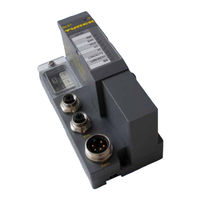
turck BL67-8XSG-PD User Manual (236 pages)
BL67 series MULTIPROTOCOL GATEWAY FOR ETHERNET
Brand:
turck
| Category:
Gateway
| Size: 10 MB
Table of Contents
Table of Contents
3
1 About this Manual
9
Documentation Concept
10
Additional Documentation
10
Explanation of Symbols Used
11
Further Notes
11
Warnings
11
General Notes
12
Prescribed Use
12
Notes Concerning Planning/Installation of this Product
12
List of Revisions
13
2 Bl67 Philosophy
15
The Basic Concept
16
Flexibility
17
Easy to Handle
17
The BL67 Components
18
Gateways
18
Electronic Modules
19
Base Modules
19
Power Feeding Modules
19
End Plate
20
3 Properties: Gateway
21
General Technical Data
23
Function
23
Version Overview
23
Supported I/O-Modules (Protocol Dependent)
24
Quickconnect (QC) and Fast Start-Up (FSU)
26
Technical Data
27
Top View BL67-GW-EN (VN < 03-00)
27
Top View BL67-GW-EN (VN ≥ 03-00)
28
Gateway Structure
28
Technical Data
29
Connection Options
33
Fieldbus Connection
33
Bl67-Gw-En < Vn 03-00
33
Ethernet-Connection for QC-/FSU-Applications
33
Voltage Supply Via 7/8"-Connector
34
Service-Interface Female PS/2 Connector (VN < 03-00)
35
Connection Using Commercially Available Cables
35
Connection with I/O-ASSISTANT-Connection Cable
35
Address Assignment
37
LED Behavior
37
Default Setting of the Gateway
38
Resetting the IP-Address, Switch Position "000
38
Address Setting Via Rotary Coding Switch (Rotary Mode)
39
Address Setting Via Bootp-Mode (300)
40
Address Setting Via DHCP-Mode (400)
40
Address Setting Via PGM-Mode (500)
41
Address Setting Via the Mode PGM-DHCP (Universal Mode, 600)
42
F_Reset (Reset to Factory Settings, 900)
42
Permanent IP-Address Assignment Using the Rockwell BOOTP/DHCP-Server
42
Profinet
42
Addressing Via I/O-ASSISTANT 3 (FDT/DTM)
43
Address Assignment Via Web Server (Only VN ≥ 03-00)
46
Reset to Factory Settings
47
Web Server - Remote Access/Configuration (Only VN ≥ 03-00)
48
Safety in the Web Server
48
IP Address
48
Home
49
Gateway Diagnostics
49
Ethernet Statistics
50
Links
51
Login/Password
51
Change Admin Password
52
Network Configuration
53
Change Network Parameters (Port Settings, IP Address, Etc.)
53
Gateway Configuration
54
Configuration of the Field Bus Interface
54
Reboot
54
Reset to Factory Defaults
54
Slot Parameters
55
Parameterization of the In-/Outputs
55
Usage of Mobile Devices
56
Web Server Logout
56
Deactivating the Web Server
57
Status and Control Word of the BL67-Stations
58
Status Word
58
Control Word
58
Meaning of the Status Bits
58
SET Button
59
Status Indicators/Diagnostic Messages Gateway
60
Diagnostic Messages Via Leds
60
Parameters of the I/O-Modules
63
Diagnostics of the I/O-Modules
64
4 Implementation of Ethernet/Ip™
65
4 Implementation of Ethernet/Ip
65
The Ethernet/Ip™ Communications Profile
66
Communications Profile for BL67
67
QC - Quickconnect
68
General
68
Quickconnect in BL67
68
Quick Connect Via Class Instance Attribute
69
Quickconnect Via Configuration Assembly
69
Quickconnect Via Web Server
69
Device Level Ring (DLR)
70
Diagnostic Messages Via the Process Data
71
Summarized Diagnostics
71
Scheduled Diagnostics
71
Classes and Instances of the Ethernet/Ip™ Stations
72
Ethernet/Ip™ Standard Classes
72
Identity Object (0×01)
73
Assembly Object (0×04)
75
Process Data Instances
76
Mapping of Process Data
77
TCP/IP Interface Object (0×F5)
78
Ethernet Link Object (0×F6)
82
DLR Object (0×47)
85
QOS Object (0×48)
86
VSC-Vendor Specific Classes
87
Class Instance of the VSC
87
Gateway Class (VSC 100, 64H)
88
Class Instance
88
Process Data Class (VSC102, 66H)
91
Class Instance
91
Object Instance 1
91
Object Instance 1, Standard Output Process Data (Compressed)
91
Object Instance 2
91
Object Instance 3, Diagnostic Instance
92
Object Instance 4, COS/CYCLIC Instance
92
Miscellaneous Parameters Class (VSC 126)
93
Instance 1 (Port 1)/Instance 2 (Port 2)
93
5 Application Example: Bl67-Gw-En with Ethernet/Ip™ (allen Bradley)
95
General Notes
96
Used Hard-/ Software
96
Hardware
96
Software
96
Network Configuration
97
Configuration of the Network in "RS Logix 5000
97
Configuration of the Controller
97
Configuration of the Ethernet/Ip™ Bridge
98
Configuring the BL67-Station
99
Downloading the I/O Configuration
102
I/O Data Mapping
104
Process Data Access
106
Setting Outputs
106
Example Program
107
Activating Quickconnect
109
6 Implementation of Modbus TCP
111
Common Modbus Description
112
Protocol Description
113
Implemented Modbus Functions
116
Modbus Registers
117
Structure of the Packed In-/Output Process Data
121
Packed Input Process Data
121
Packed Output Process Data
122
Status/Diagnosis
122
Data Width of the I/O-Modules in the Modbus-Register Area
123
Register 100Ch: "Gateway Status
124
Register 1130H: "Modbus Connection Mode
125
Register 1131H: "Modbus Connection Timeout
125
Register 0×113C and 0×113D: "Restore Modbus-Connection-Parameters
125
Register 0×113E and 0×113F: "Save Modbus-Connection-Parameters
125
The Service Object
126
Indirect Reading of Registers
127
Bit Areas: Mapping of Input-Discrete- and Coil-Areas
128
Indirect Writing of Registers
128
Data Mapping in the Input-Discrete- and Coil-Areas
128
Output Module Behavior in Case of an Error
129
7 Application Example: Bl67-Gw-En with Modbus TCP (Codesys Win V3)
131
Used Hard-/Software
132
Hardware
132
Software
132
Network Configuration
133
Programming with CODESYS
134
Predefined Feature Sets
134
Creating a New Project
135
Defining the Communication Settings
137
Define a Gateway
137
Setting the Communication Path
138
Adding the Ethernet Adapter
139
Adding the Modbus Master
140
Adding a Modbus TCP Slave
141
Programming (Example Program)
143
Small Example Program
143
CODESYS: Global Variables
144
Global Variable List
144
Modbus Channels
145
Modbus Data Mapping
146
Setting the Modbus-Channels (Examples) and Data Mapping
148
Building, Login and Start
157
Reading out the Process Data
159
Diagnosis Evaluation
160
Evaluation of the Status Word of the BL67-Station (%IW1)
160
Evaluation on the Group Diagnosis
161
Evaluation of the Module Diagnosis Information
163
8 Implementation of Profinet
165
Profinet
166
FSU - Fast Start-Up (Prioritized Startup)
168
General
168
FSU in BL67
168
Ethernet-Connection for BL67 in QC-/FSU-Applications
168
MRP (Media Redundancy Protocol)
169
Address Assignment
169
Default Values
170
GSDML File
170
Diagnosis in PROFINET
171
Gateway Error Codes
171
Channel-Specific Error Codes of the I/O-Modules
172
Meaning of the PROFINET Error Codes for the BL67 I/O-Modules
173
Parameterization
176
Gateway Parameters
176
Description of the Gateway Parameters
176
I/O Module Parameters
179
Description of User Data for Acyclic Services
180
Description of the Acyclic Gateway User Data
180
Description of the Acyclic Module User Data
181
9 Application Example: Bl67-Gw-En with Profinet (S7)
183
Application Example
184
General
184
Example Network
184
New Project in the SIMATIC Manager
185
Setting the PG/PC-Interface
185
Installation of the GSDML-Files
186
Adding PROFINET Network Nodes
190
Adding a BL67-Gateway and Configuring the BL67-Station
191
Configuring the BL67-Station
192
Scanning the Network for PROFINET Nodes
193
Device Name Assignment BL67-Gateway
194
PROFINET Neighborhood Detection Via LLDP
195
Necessary Setting of the PROFINET-Controller
195
Configuring the Neighborhood Detection
196
Online Topology Detection
198
Fast Start-Up - Configuration of Fieldbus Nodes
199
Prioritized Stat-Up - Activation at PN-IO
199
Setting the Ethernet-Ports (Port 1 and Port 2)
200
Diagnosis with Step 7
201
Diagnostic Messages in the Hardware Configuration
201
Diagnostic Telegram with Error Code
202
10 Guidelines for Station Planning
203
Module Arrangement
204
Random Module Arrangement
204
Complete Planning
205
Maximum System Extension
205
Creating Potential Groups
206
Plugging and Pulling Electronics Modules
206
Extending an Existing Station
207
Firmware Download
208
11 Guidelines for Electrical Installation
209
General Notes
210
General
210
Cable Routing
210
Cable Routing Inside and Outside of Cabinets
210
Lightning Protection
211
Transmission Media
211
Cable Routing Outside Buildings
211
Potential Relationships
212
General
212
Electromagnetic Compatibility (EMC)
213
Ensuring Electromagnetic Compatibility
213
Grounding of Inactive Metal Components
213
PE Connection
213
Earth-Free Operation
213
Mounting Rails
214
Shielding of Cables
215
Potential Compensation
216
Switching Inductive Loads
216
Protection against Electrostatic Discharge (ESD)
216
12 Appendix
217
Changing the IP Address of a PC/ Network Interface Card
218
Changing the IP Address in Windows
218
Changing the IP Address Via Pactware™ FDT/DTM (I/O-ASSISTANT V3)
220
Deactivating/ Adapting the Firewall in Windows
221
Addressing Via DHCP
223
Nominal Current Consumption of Modules on Ethernet
225
Ident Codes of the BL67-Modules
227
Advertisement
turck BL67-8XSG-PD Manual (178 pages)
MODULAR FIELDBUS I/O-SYSTEM IN IP67
Brand:
turck
| Category:
I/O Systems
| Size: 5 MB
Table of Contents
Modbus Tcp
4
Profibus-Dp
8
Maximum System Extension
9
General Technical Data
20
Pin Configuration
86
Profibus-Dp
126
Advertisement
Related Products
turck BL67-8DI-P
turck BL67-8DI-PD
turck BL67-8DO-0.5A-N
turck BL67-8DO-0.5A-P
turck BL67-8DO-R-NO
turck BL67-8XSG-P
turck BL67-4DI-P
turck BL67-4DO-4A-P
turck BL67-4AO-V
turck BL67-4DI4DO-PD
turck Categories
Accessories
Security Sensors
I/O Systems
Measuring Instruments
Control Unit
More turck Manuals
Login
Sign In
OR
Sign in with Facebook
Sign in with Google
Upload manual
Upload from disk
Upload from URL