Sign In
Upload
Manuals
Brands
turck Manuals
I/O Systems
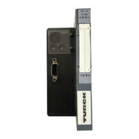
BL20-GW-PBDB-1.5MB-S
turck BL20-GW-PBDB-1.5MB-S Manuals
Manuals and User Guides for turck BL20-GW-PBDB-1.5MB-S. We have
1
turck BL20-GW-PBDB-1.5MB-S manual available for free PDF download: Hardware And Engineering
turck BL20-GW-PBDB-1.5MB-S Hardware And Engineering (450 pages)
BL20 series; BL20-1AI series; BL20-1AO series; BL20-S3x-SBB series
Brand:
turck
| Category:
I/O Systems
| Size: 5 MB
Table of Contents
Table of Contents
5
1 About this Manual
15
Documentation Concept
16
Description of Symbols Used
17
General Information
18
Prescribed Use
18
Notes Concerning Planning /Installation of this Product
18
List of Revisions
19
2 Bl20 Philosophy
21
The Basic Concept
22
BL20 Components
23
Gateways
23
Gateways with Integrated Power Supply
23
Gateways Without Power Supply
23
Power Distribution Modules
24
Electronics Modules
24
Base Modules
25
Bl20 Eco
26
End Plate
27
End Bracket
27
Jumpers
28
Shield Connection (Gateway)
28
Marking Material
29
Shield Connection, 2-Pole for Analog Modules
29
3 General Technical Data of Bl20 Modules
31
Introduction
32
Abbreviations
33
Module Abbreviations
33
Station Dimensions
36
Dimensions for Electronics Modules
36
Dimensions for Base Modules
36
Dimension Drawings
36
Dimensions of the BL20-ECO Modules
40
General Technical Data of a BL20 Station
41
Approvals
43
Technical Data of Base Modules
43
4 Power Distribution Modules
45
Power Feeding Modules
46
Module Overview
46
Power Feeding Module, 24 V DC, with Diagnostics
47
Power Feeding Module, 120/230 V AC, with Diagnostics
50
Bus Refreshing Modules
53
Module Overview
53
Bus Refreshing Module with Diagnostics
54
5 Digital Input Modules
59
General
61
Module Overview
61
Digital Input Module, 2DI, 24 V DC, Positive Switching (Sinking)
62
Technical Data
63
Diagnostic and Status Messages
63
Module Parameters
64
Base Modules
64
Wiring Diagrams
64
Digital Input Module, 2DI, 24 V DC, Negative Switching (Sourcing)
66
Technical Data
67
Diagnostic and Status Messages
67
Module Parameters
68
Base Modules
68
Wiring Diagrams
68
Digital Input Module, 2DI, 120/230 V AC
70
Technical Data
71
Diagnostic and Status Messages
71
Module Parameters
72
Base Modules
72
Wiring Diagrams
72
Digital Input Module, 4DI, 24 V DC, Positive Switching (Sinking)
74
Technical Data
75
Diagnostic and Status Messages
75
Module Parameters
76
Base Modules
76
Wiring Diagrams
77
Digital Input Module, 4DI, 24 V DC, Negative Switching (Sourcing)
78
Technical Data
79
Diagnostic and Status Messages
79
Module Parameters
80
Base Modules
80
Wiring Diagrams
81
Digital Input Module, 4DI, NAMUR
82
Technical Data
83
Diagnostic and Status Messages
83
Module Parameters
84
Base Modules
85
Wiring Diagrams
85
Digital Input Module, BL20 Economy, 8DI, 24 V DC, Positive Switching (Sinking)
86
Technical Data
87
Diagnostic and Status Messages
87
Wiring Diagrams
88
Digital Input Module, 16DI, 24 V DC, Positive Switching (Sinking)
89
Technical Data
90
Diagnostic and Status Messages
90
Base Modules
91
Module Parameters
91
Wiring Diagrams
92
Digital Input Module, BL20 Economy, 16DI, 24 V DC, Positive Switching (Sinking)
93
Technical Data
94
Diagnostic and Status Messages
94
Wiring Diagrams
95
Digital Input Module, 32DI, 24 V DC, Positive Switching (Sinking)
96
Technical Data
97
Diagnostic and Status Messages
98
Module Parameters
98
Base Modules
98
Wiring Diagrams
99
6 Analog Input Modules
101
General
104
Shielding
104
Analog Value Representation
104
Module Overview
105
Analog Input Module, 1AI, 0/4
106
Technical Data
107
Diagnostic and Status Messages
107
Module Parameters
108
Base Modules
108
Wiring Diagrams
109
Bit Value Representation
110
Bit Value Representation (Left-Justified)
110
Analog Input Module, 2AI, 0/4
111
Technical Data
112
Diagnostic and Status Messages
112
Module Parameters (Per Channel)
113
Base Modules
113
Wiring Diagrams
114
Measurement Value Representation
115
Bit Value Representation
115
Bit Value Representation (Left-Justified)
115
Analog Input Module, 1AI, -10/0
116
Technical Data
117
Module Parameters
118
Base Modules
118
Wiring Diagrams
119
12-Bit-Representation (Left-Justified)
120
16-Bit-Representation
120
Analog Input Module, 2AI, -10/0
121
Technical Data
122
Diagnostic and Status Messages
122
Module Parameters (Per Channel)
123
Base Modules
123
Wiring Diagrams
124
Measurement Value Representation
125
12-Bit-Representation (Left-Justified)
125
16-Bit-Representation
125
Analog Input Module, 2AI, Pt-/Ni-Sensors
126
Technical Data
127
Diagnostic and Status Messages
127
Module Parameters (Per Channel)
128
Base Modules
129
Analog Input Module, 2AI, Thermocouple
133
Diagnostic and Status Messages
135
Module Parameters (Per Channel)
136
Base Modules
137
Wiring Diagrams
137
Measurement Value Representation
138
12-Bit-Representation (Left-Justified)
138
16-Bit-Representation
138
Analog Input Module, 4AI, Voltage/ Current
140
Technical Data
140
Diagnostic and Status Messages
141
Module Parameters (Per Channel)
142
Wiring Diagrams
143
Measurement Value Representation
144
Bit Value Representation
144
Bit Value Representation (Left-Justified)
145
Analog Input Module, 8AI Voltage/Current and 4 Pt/Ni
146
Technical Data
147
Diagnostic and Status Messages
148
Module Parameters (Per Channel)
150
Wiring Diagrams
151
Standard Value Representation for Voltage/ Current
152
16-Bit-Representation
152
Process Input Data
152
12-Bit-Representation (Left-Justified)
154
Extended Range - Value Representation for Voltage/Current
155
16-Bit-Representation
155
12-Bit-Representation
158
Value Representation for Process Automation (NE43) for Voltage/Current
160
16-Bit-Representation
160
12-Bit-Representation (Left-Justified)
162
Standard Value Representation for Pt-/ Ni- and Resistance Measurement
164
16-Bit-Representation
164
Wire Break and Short Circuit Diagnostic in Pt-/Ni-Measurement
164
12-Bit-Representation (Left-Justified)
167
Analog Input Module, 2AI Current, HART
171
Technical Data
172
Diagnostic and Status Messages
172
Module Parameters (Per Channel)
175
Base Modules
176
Wiring Diagrams
177
Process Input Data
178
Standard Value Representation, 16 Bit Integer
179
Extended Range - Value Representation, 16-Bit-Representation
180
Value Representation Process Automation (NE 43), 16 Bit Representation
181
7 Digital Output Modules
183
General
185
Module Overview
186
Digital Output Module, 2DO, 0.5 A, Positive Switching (Sourcing)
187
Technical Data
188
Diagnostic and Status Messages
189
Module Parameters
189
Base Modules
189
Wiring Diagrams
190
Digital Output Module, 2DO, 0.5 A, Negative Switching (Sinking)
191
Technical Data
192
Diagnostic and Status Messages
193
Module Parameters
193
Base Modules
193
Wiring Diagrams
194
Digital Output Module, 2DO, 2 A, Positive Switching (Sourcing)
195
Technical Data
196
Diagnostic and Status Messages
197
Module Parameters
197
Base Modules
197
Wiring Diagrams
198
Digital Output Module, 4DO, 0.5 A, Positive Switching (Sourcing)
199
Technical Data
200
Diagnostic and Status Messages
201
Module Parameters
201
Base Modules
201
Wiring Diagrams
202
Digital Output Module, BL20 Economy, 8DO, 0,5 A, Positive Switching (Sourcing)
203
Technical Data
204
Diagnostic and Status Messages
205
Wiring Diagrams
205
Digital Output Module, 16DO, 0,5 A, Positive Switching (Sourcing)
206
Technical Data
207
Diagnostic and Status Messages
208
Module Parameters
208
Base Modules
209
Wiring Diagrams
209
Digital Output Module, BL20 Economy, 16DO, 0,5 A, Positive Switching (Sourcing)
210
Technical Data
211
Diagnostic and Status Messages
212
Wiring Diagrams
212
Digital Output Module, 32DO, 0,5 A, Positive Switching (Sourcing)
213
Technical Data
214
Diagnostic and Status Messages
215
Base Modules
216
Wiring Diagrams
216
Digital Output Module, 2DO, 0.5A, 120/230 VAC
217
Technical Data
218
Diagnostic and Status Messages
219
Module Parameters
219
Base Modules
219
Wiring Diagrams
220
8 Analog Output Modules
221
General
223
Resolution of Analog Value Representations
223
Shielding
223
Module Overview
223
Analog Output Module, 1AO, 0/4
224
Technical Data
224
Diagnostic and Status Messages
225
Module Parameters
225
Base Modules
226
Wiring Diagrams
226
Measurement Value Representation
226
12-Bit-Representation (Left-Justified)
226
16-Bit-Representation
226
Analog Output Module, 2AO, 0/4
228
Technical Data
228
Diagnostic and Status Messages
229
Module Parameters (Per Channel)
229
Base Modules
230
Wiring Diagrams
230
Measurement Value Representation
230
16-Bit-Representation
230
12-Bit-Representation (Left-Justified)
231
Analog Output Module, 2AO, -10/0
232
Technical Data
233
Diagnostic and Status Messages
234
Module Parameters (Per Channel)
234
Base Modules
234
Wiring Diagrams
235
Measurement Value Representation
235
12-Bit-Representation (Left-Justified)
235
16-Bit-Representation
235
Analog Output Module, 4AO, Voltage/ Current, Economy
236
Technical Data
237
Diagnostic and Status Messages
238
Module Parameters (Per Channel)
238
Wiring Diagrams
240
Standard Value Representation
241
16-Bit-Representation
241
12-Bit-Representation (Left-Justified)
242
Extended Range - Value Representation for Voltage/Current
244
16-Bit-Representation
244
12-Bit-Representation (Left-Justified)
247
Value Representation for Process Automation (NE 43)
248
16-Bit-Representation
248
12-Bit-Representation (Left-Justified)
249
Analog Output Module, 2AO Current, HART
250
Technical Data
251
Diagnostic and Status Messages
252
Module Parameters (Per Channel)
254
Base Module
257
Wiring Diagram
257
Process Input Data
258
Process Output Data
258
Standard Value Representation, 16-Bit-Representation)
258
Extended Range - Value Representation, 16-Bit-Representation
259
Value Representation Process Automation (NE 43), 16-Bit-Representation
261
9 Relay Modules
263
General
264
Load Limit Curve with Resistive Load
264
Module Overview
265
Relay Module, 2 Normally-Closed Contacts
266
Technical Data
267
Module Parameters
268
Base Modules
268
Diagnostic and Status Messages
268
Wiring Diagrams
269
Relay Module, 2 Normally-Open Contacts
271
Technical Data
272
Diagnostic and Status Messages
273
Module Parameters
273
Base Modules
273
Wiring Diagrams
274
Relay Module, 2 Changeover Contacts
276
Technical Data
276
Diagnostic and Status Messages
277
Module Parameters
277
Base Modules
278
Wiring Diagrams
278
10 Technology Modules
281
Module BL20-1CNT-24VDC
284
Selecting Counter or Measurement Mode
284
Counter Modes
284
Counter Modes
285
Main Count Direction
285
Maximum Count Range
285
Limit Values of Count Mode
286
Minimum Number of Count Pulses between Internal Events
286
Continuous Counting
287
Time between Direction Signal (B) and Counter Signal (A)
287
Single-Action Count
289
Periodical Count
292
Measurement Mode
296
Frequency Measurement
296
Revolutions Measurement
297
Limit Value Monitoring
299
Period Duration Measurement
299
Range Defined Via the Control Interface/Process Output
299
Functions and Explanations
300
Software Gate and Hardware Gate
300
Synchronization
300
Latch Retrigger Function
302
Behavior of the DI Digital Input
303
Behavior of the Digital Outputs DO1/DO2
303
Hysteresis for Digital Output DO1/DO2
305
Signal Evaluation Options for Rotary Sensors
306
Load Value Direct/In Preparation
307
Pulse and Direction
307
Pulse Duration on Reaching the Reference Value
307
Resetting the Status Bit
308
Transfer of Values/Load Function
308
Transfer of Values/Load Function
309
Technical Features
310
Technical Data
312
Diagnostic and Status Messages
314
Base Modules
316
Wiring Diagrams
316
RS232 Interface BL20-1RS232
317
Data Transfer Method
317
Data Exchange
317
Process Input Data (Pdin)
317
Meaning of the Data Bits
318
Schematic Diagram of the Receive Sequence
319
Process Output Data (Pdout)
319
Schematic Diagram of the Transmit Sequence
321
Technical Data
321
Technical Data
322
Diagnostic and Status Messages
323
Diagnosis Via Leds
323
Diagnosis Via Software
323
Module Parameters
324
Base Modules
325
Wiring Diagrams
325
Pin Assignment
326
RS485/422 Interface BL20-1RS485/422
327
Transmission Procedure
327
Data Exchange
327
Process Input Data (Pdin)
327
Meaning of the Data Bits
328
Schematic Diagram of the Receive Sequence
329
Process Output Data (Pdout)
329
Schematic Diagram of the Transmit Sequence
331
Technical Data
331
Technical Data
333
Diagnosis Via Leds
334
Diagnosis Via Software
334
Diagnostic and Status Messages
334
Module Parameters
335
Base Modules
336
Wiring Diagrams
336
Signal Types
337
SSI Interface BL20-1SSI
338
Transmission Procedure
338
Data Exchange
338
Internal Registers - Read and Write Operations
338
Register Access and Meaning
339
Comparison Value 1, Comparison Value 2
341
Lower Limit, Upper Limit
342
Offset Function / Load Value
343
Status Messages of the SSI Encoder
343
Resetting the Register Bank
344
Technical Data
345
Diagnostic and Status Messages
346
Diagnosis Via Leds
346
Module Parameters
347
Base Modules
348
Wiring Diagrams
349
Bl20-E-1Swire
350
Features
350
Function Parameterization
351
MC (Moeller Conformance)
357
Other Parameters
357
Diagnostics
357
Technical Features
358
Module Parameters
364
Moeller SWIRE Conformance Criteria
369
Special System Behavior with the "Moeller Conformance" Function
369
System Behavior with the Configuration Checks
370
11 Mounting and Wiring
371
General Mounting Rules
372
Mechanical Mounting
372
Mounting the Gateway
372
Mechanical Mounting
373
Mounting the Base Module (Block or Slice Design)
374
Mounting Slot Identification and Color Markers
375
Mounting Slot Identification
375
Color Markers
376
Jumpers for Relay Modules
377
Mounting End Brackets and End Plates
378
End Bracket
378
End Plate
379
Wiring of Screw Connection
380
Wiring with Tension Clamp Connections
380
Mounting the Electronics Modules
381
Prevention of False Mounting
381
Switchgear Cabinet Layout
383
Dismounting from the Mounting Rail
384
Dismounting of a Single Component
384
Dismounting Electronics Modules
385
Dismounting Base Modules
386
Dismounting End Brackets and Eend Plates
386
Dismounting the Gateway
389
Plugging and Pulling Electronics Modules
390
Handling the BL20 Economy Modules
391
Insertion of the Conductor
391
Removal of the Conductor
391
12 Module Labeling
395
General Notes
395
Colors
396
Gateways
397
Electronics Modules
398
Base Modules
399
Labels
401
13 BL20-Approvals for Zone 2/ Division
403
14 Appendix
405
Analog Value Representation (Analog Input Modules)
406
Equations for 16 Bit Representation
408
Current Values from 0 to 20 Ma
408
Current Values from 4 to 20 Ma
408
Temperature- and Resistance Values (BL20-2AI-PT/NI-2/3)
408
Example of the Conversion of Negative Numerical Values
409
Temperature- and Voltage Values (BL20-2AI-THERMO-PI)
411
Voltage Values from -10 to 10 V DC
412
Voltage Values from 0 to 10 V DC
412
Equations for 12-Bit-Representation
413
Current Values from 0 to 20 Ma
413
Current Values from 4 to 20 Ma
413
Temperature and Resistance Values (BL20-2AI-PT/NI-2/3)
414
Temperature- and Voltage Values (BL20-2AI-THERMO-PI)
416
Voltage Values from 0 to 10 V DC
417
Voltage Values from -10 to 10 V DC
418
Analog Value Representation (Analog Output Modules)
419
Equations for 16 Bit Representation
419
Conversion of the Decimal Values into Hexadecimal/ Binary Values
420
Voltage Values from -10 to 10 V DC
420
Current Values from 0 to 20 Ma
421
Equations for 12-Bit-Representation
421
Current Values from 4 to 20 Ma
422
Voltage Values from 0 to 10 V DC
422
Voltage Values from -10 to 10 V DC
423
Conversion of the Negative Decimal Values into Hexadecimal/ Binary Value
424
Identcodes of the BL20-Modules
425
Nominal Current Consumption and Power Loss
427
Nominal Current Consumption of the BL20 Modules from Supply Terminal I
427
Nominal Current of the BL20 Modules on the Module Bus I
429
Power Loss of the BL20 Modules
431
Acronyms
433
Electronic and Base Modules
435
Conversion Table Decimal to Hexadecimal
437
Parameter Gateway - Assignment in Hexadecimal Format
438
Parameter 4
438
Parameter 5
440
15 Glossary
443
Advertisement
Advertisement
Related Products
turck BL20-GW-PBDP-1.5MB
turck BL20-GWBR-PBDP
turck BL20-2DO-R-CO
turck BL20-2DO-R-NO
turck BL20-S3S-SBB
turck BL20-S3T-SBB
turck BL20-P3T-SBB
turck BL20-KO/2
turck BL20-KLBU/T
turck BL20-2DI-24VDC-P
turck Categories
Accessories
Security Sensors
I/O Systems
Control Unit
Measuring Instruments
More turck Manuals
Login
Sign In
OR
Sign in with Facebook
Sign in with Google
Upload manual
Upload from disk
Upload from URL