Sign In
Upload
Manuals
Brands
TSE Manuals
Laboratory Equipment
Calorimetry PhenoMaster
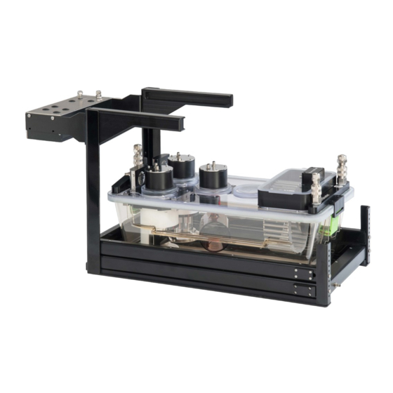
TSE Calorimetry PhenoMaster Manuals
Manuals and User Guides for TSE Calorimetry PhenoMaster. We have
1
TSE Calorimetry PhenoMaster manual available for free PDF download: Hardware Operating Instructions
TSE Calorimetry PhenoMaster Hardware Operating Instructions (70 pages)
Brand:
TSE
| Category:
Laboratory Equipment
| Size: 5 MB
Table of Contents
Table of Contents
3
1 Introduction
7
2 Instructions for Safe Operation
8
General Safety Instructions
8
Proper Use
8
3 Operating Principle
9
4 PC Requirements
9
5 Installation Drivers, Interface, Software
10
USB Interface
10
Installing *.Inf File (TSE USB Adapter*)
10
Fig. 1 Default Installation Path - Drivers Destination Location
10
Wireone Driver
12
6 Connecting Devices - General
16
7 Cage Rack
16
8 System Software
16
9 Performing a Measurement
16
10 Maintenance and Cleaning
17
Cage
17
Cage Lid
17
Calorimetry Cage Lid
17
Fig. 2 Calorimetry Cage Lid
19
Air Supply Pump
20
Exchanging Filter
21
Fig. 3 Air Pump (Top View)
21
Fig. 4 Filter Cover Removed
21
Overpressure Valve
22
Fig. 5 Filter Removed
22
Chamber Block Change
23
Troubleshooting
24
Fig. 6 Diaphragm Protective Switch Deactivated
24
Fig. 7 Diaphragm Protective Switch Activated (Pump Powered OFF)
24
Fig. 8 Diaphragm Protective Switch Deactivated
24
Vacuum Pump
25
Chamber Block Change
25
Exchanging Protection Air Filter
25
Exchanging Disk Filter
26
Fig. 9 Disassembling Discus Filter (1)
26
Air Drying Unit
27
Tubing
27
Fig. 10 Disassembling Discus Filter (2)
27
Replacing Flowmeter Battery
28
Fig. 11 Replacement of Flowmeter Battery
28
11 Calorimetry Measurement
29
Overview Devices and Connections
29
Push Principle Respirometry (Overpressure Principle)
30
Calosys Module to be Operated with Manual Calibration
30
Fig. 12 Schematic Diagram of Calosys Module - Push Principle Respirometry - W/O Calibration Unit - Analog Read-Out - 8-Place System
30
Calosys Module to be Operated with Automatic or Manual Calibration
32
Fig. 13 Schematic Diagram of Calosys Module - Push Principle Respirometry - W/ Calibration Control Unit - 8-Place System
32
Calosys Module Including Multiple Calorimetry Control Units
33
Fig. 14 Schematic Diagram of Calosys Module - Push Principle Respirometry - W/ Multiple Calorimetry Control Units - Digital Read-Out - 8-Place System
34
Pull Principle Respirometry (Underpressure Principle)
36
Calosys Module to be Operated with Manual Calibration
36
Fig. 15 Schematic Diagram of Calosys Module - Pull Principle Respirometry - W/O Calibration Control Unit - Analog Read-Out - 8-Place System
36
Calosys Module to be Operated with Automatic or Manual Calibration
38
Fig. 16 Schematic Diagram of Calosys Module - Pull Principle Respirometry - W/ Calibration Control Unit - 8-Place System
38
Calosys Module Including Multiple High-Speed Sensor Units
40
Fig. 17 Schematic Diagram of Calosys Module - Pull Principle Respirometry - W/ Multiple High-Speed Sensor Units - Digital Read-Out - 32-Place System
41
Calorimetry Process Control Unit
43
Connections Calorimetry Process Control Unit
44
Fig. 18 Calorimetry Master Control Unit
44
Fig. 19 Calorimetry Master Control Unit - Rear View
44
Connections Calorimetry Master Process Control Unit
45
Connections Calorimetry Master Process Control and High-Speed Sensor Unit
46
Fig. 20 Calorimetry Master Control Unit - Rear View
46
Connections Calorimetry Slave Process Control Unit
47
Mass Flow Controllers in Calorimetry Control Unit
47
Fig. 21 Calorimetry Slave Control Unit - Rear View
47
Fig. 22 Flowmeter
48
Setting Sample Flow on Calorimetry Master Control Unit
49
Combination Sensor for O2 and CO2 Concentration in Calorimetry Master Control Unit49
49
O2 Sensor - Working Principle
49
Fig. 23 Rotary Knob MFC Sample Flow at the Calorimetry Control Unit
49
CO2 Sensor - Working Principle
50
Temperature Sensor
50
Analogous Temperature Sensor
50
Digital Temperature Sensor
51
Calibration Master Process Control Unit
51
Connections Calibration Master Process Control Unit
51
Fig. 24 Calibration Master Control Unit - Front Panel
51
Fig. 25 Gas Pressure Display
52
Fig. 26 Calibration Master Control Unit - Rear Panel
52
Connections Calibration Slave Process Control Unit
53
Fig. 27 Calibration Slave Control Unit
53
Sample Switch Unit
54
Connections Sample Switch Unit
54
Fig. 28 Ports/Connectors of Sample Switch Unit for 16 Animal Cages
54
Information about Reference Air
55
Connecting PC
55
Air Supply Pump
55
Fig. 29 PC Ports
55
Fig. 30 Air Supply Pump
56
General
57
Installation
57
Connections
57
Operation
58
Fig. 31 Pressure Control Valve
58
Vacuum Pump
59
Fig. 32 Vacuum Pump
59
Installation
60
Connections
61
Fig. 33 Pressure Control Valve
61
Operation
62
Protection Air Filter
62
Connections Protection Air Filter
62
Fig. 34 Connections Protection Air Filter
63
Fig. 35 Flow Direction
63
Air Drying Unit
64
Air Drying Unit
65
Fig. 36 1X Air Drying Unit W/ Separating Bottle
65
Air Drying Unit
66
Fig. 37 4X Air Drying Unit
66
Connections Air Drying Unit
67
Appendix
68
Example Configurations
68
Example Electrical Requirements
68
Advertisement
Advertisement
Related Products
TSE PhenoMaster
TSE Categories
Telephone
Monitor
Utility Vehicle
Engine
Construction Equipment
More TSE Manuals
Login
Sign In
OR
Sign in with Facebook
Sign in with Google
Upload manual
Upload from disk
Upload from URL