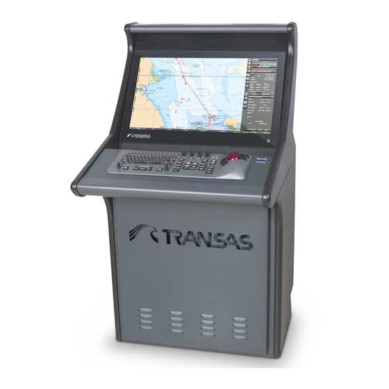
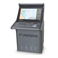
Transas NAVI-SAILOR 4000 ECDIS Manuals
Manuals and User Guides for Transas NAVI-SAILOR 4000 ECDIS. We have 2 Transas NAVI-SAILOR 4000 ECDIS manuals available for free PDF download: Installation Manual, Quick Reference Manual
Transas NAVI-SAILOR 4000 ECDIS Installation Manual (382 pages)
Brand: Transas
|
Category: Marine Equipment
|
Size: 29 MB
Table of Contents
-
Preamble
5 -
-
-
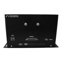
RS6 Computer14
-
-
View of UPS625
-
Structure25
-
Convection26
-
Connection27
-
Signalling29
-
Mounting31
-
Network46
-
-
-
General99
-
-
Software Upgrade125
-
-
General135
-
-
Technical Data139
-
Dimensions141
-
Technical Data145
-
-
Transas Monitors152
-
WAGO I/O Modules167
-
End Module173
-
-
-
General179
-
-
Input180
-
Summary Table180
-
-
Output189
-
-
-
-
Annex a
221 -
Annex B
255-
Parameter Value269
-
Field Formats269
-
Parameter Status270
-
Empty Fields271
-
Annex C
297-
Ship's Settings299
-
Charts Settings300
-
NMEA Output300
-
Databases300
-
NMEA Input301
-
Sensors301
-
DCU Settings303
-
Fallback303
-
Annex D
307 -
Annex E
313 -
Annex F
317-
Cabling322
-
Power Supply326
-
Rs4V2 Dimensions328
-
Memory331
-
Storage331
-
Keyboard333
-
Trackball334
-
Loudspeaker334
-
Keyboard Legend334
-
Appointment335
-
Purposes345
-
Diagrams355
-
Annex G
355
Advertisement
Transas NAVI-SAILOR 4000 ECDIS Quick Reference Manual (9 pages)
Brand: Transas
|
Category: Marine GPS System
|
Size: 7 MB
Table of Contents
Advertisement