Sign In
Upload
Manuals
Brands
Trane Manuals
Controller
Tracer UC210
User Manuals: Trane Tracer UC210 VAV Controller
Manuals and User Guides for Trane Tracer UC210 VAV Controller. We have
1
Trane Tracer UC210 VAV Controller manual available for free PDF download: Installation, Operation, And Programming
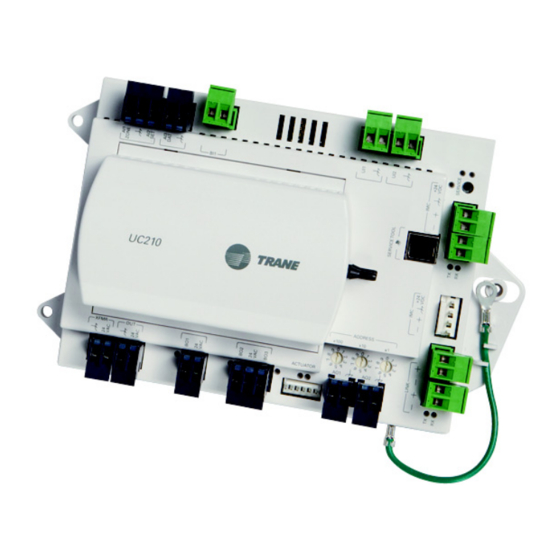
Trane Tracer UC210 Installation, Operation, And Programming (72 pages)
Programmable Variable-Air-Volume (VAV) Box Controller
Brand:
Trane
| Category:
Controller
| Size: 5 MB
Table of Contents
Table of Contents
4
Overview
6
The Bacnet Protocol
6
Controller Specifications and Dimensions
7
Shipping and Storage
9
UC210 Features
9
Controller Comparisons
10
Device Connections
11
Device Inputs/Outputs
12
Wiring Installation
13
UC210 Controller Pre-Power Check-Out
13
Transformer Recommendations
13
UC210 Controller Power Wiring
14
Guidelines
14
Bacnet MS/TP Communication Link
16
Wiring Guidelines
16
Wiring Best Practices
17
Setting up the UC210 Controller on a Bacnet Link
18
Setting the Address
18
Bacnet Networks Without a Tracer SC System Controller
19
Bacnet Networks with a Tracer SC System Controller
19
Wiring Requirements
20
Connecting the Wires
20
Power on Check
21
Application Wiring
21
Zone Sensor Wiring
21
Duct Temperature Sensor Wiring
23
Binary Wiring
23
Controller Leds
25
Tracer UC210 Controller Points and Parameters
27
Status Utility
27
Unit Summary Screen
27
Analog, Binary, and Multistate Screens
28
Controller Status Screen
29
Equipment Utility
29
Setpoints Screen
29
Setup Parameters Screen
30
Commissioning Screen
32
Configuration Screen
33
Calibration, Operation Modes, and Control
35
Calibration
35
Occupancy Modes
35
Occupied Mode
35
Unoccupied Mode
36
Occupied Standby Mode
36
Occupied Bypass Mode
36
Space Temperature Control (STC) for Single Duct and Fan-Powered Units
37
Single Duct Units
37
Fan-Powered Units
43
Ventilation Flow Control (VFC)
45
Flow Tracking (FTC)
48
Troubleshooting
49
Diagnostics
49
Troubleshooting Procedures
50
UC210 Controller Failure
50
UC210 Controller Communication Loss
51
Wired Zone Sensor Failure
52
Wired Zone Sensor Setpoint Failure
54
Airflow Sensor Failure
55
Supply/Discharge Air Temperature Sensor Failure
57
CO2 Sensor Failure
58
VAV Damper Failure
59
VAV Series Fan Failure
60
VAV Parallel Fan Failure
61
PSC (Permanent Split Capacitor) Variable Speed Motor Check
62
VAV Electric Heat Stage Failure
63
VAV Modulating Hot Water Failure
64
Trane/Honeywell Proportional Valve Check out
65
Appendix: Typical Trane Factory Wiring Diagrams
67
Additional Resources
69
Index
70
Advertisement
Advertisement
Related Products
Trane Tracer UC600
Trane Tracer UC400
Trane UG30
Trane Tracer UC400-B
Trane TRACER CH532
Trane Tracer ZN.520
Trane Tracer ZN524
Trane Tracer ZN521
Trane Tracer VV550
Trane Tracer VV551
Trane Categories
Air Conditioner
Heat Pump
Chiller
Air Handlers
Furnace
More Trane Manuals
Login
Sign In
OR
Sign in with Facebook
Sign in with Google
Upload manual
Upload from disk
Upload from URL