Sign In
Upload
Manuals
Brands
Toshiba Manuals
Air Conditioner
MCY-MHP1006HT8-C Series
User Manuals: Toshiba MCY-MHP1006HT8-C Series Air
Manuals and User Guides for Toshiba MCY-MHP1006HT8-C Series Air. We have
2
Toshiba MCY-MHP1006HT8-C Series Air manuals available for free PDF download: Service Manual
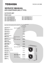
Toshiba MCY-MHP1006HT8-C Series Service Manual (191 pages)
Brand:
Toshiba
| Category:
Air Conditioner
| Size: 48 MB
Table of Contents
Table of Contents
2
Original Instruction
5
Warning Indications on the Air Conditioner Unit
7
Precautions for Safety
8
Declaration of Conformity
13
Specifications
13
New Refrigerant (R410A)
14
Explanation of Symbols
15
Product Summary
16
Outdoor Unit
16
Connectable Indoor Units
16
Branching Joints and Headers
18
PMV Kit
18
Construction Views
19
Wiring Diagram
21
Parts Rating
23
Outdoor Unit
23
Outdoor Inverter
23
Parts Layout in Outdoor Unit
24
Parts Layout in Inverter Assembly
25
Outdoor (Inverter) Print Circuit Board
26
Interface P.C. Board (MCC-1639)
26
Inverter P.C. Board for Compressor (MCC-1729) A3-IPDU
27
Fan Motor IPDU (MCC-1728)
28
Noise Filter (MCC-1733)
29
Refrigerant Piping Systematic Drawing
30
Control Outline
32
Applied Control for Outdoor Unit
39
Outdoor Fan High Static Pressure Shift
39
Priority Operation Mode Setting
39
Applied Control of Outdoor Unit
41
Optional P.C. Board of Outdoor Unit Installation
41
Power Peak-Cut Control (Standard)
43
Power Peak-Cut Control (Extended)
44
Snowfall Fan Control
45
External Master on / off Control
45
Night Operation (Sound Reduction) Control
46
Operation Mode Selection Control
47
Error / Operation Output
48
Test Operation
49
Procedure and Summary of Test Operation
49
Check Items before Test Operation (before Powering-On)
50
Check at Main Power-On
56
Address Setup
57
Precautions
57
Address Setup and Check Procedure
57
Address Setup Procedure
58
Address Setting Procedure
58
Check after Address Setup When Central Control System Is Connected
72
Troubleshooting in Test Operation
73
A Check Code Is Displayed on the Remote Controller
73
Operation from the Indoor Remote Controller Is Not Accepted, and a Check Code Is Displayed on the 7-Segment Display of the Interface P.C. Board of the Outdoor Unit
74
There Is no Display of a Check Code on the 7-Segment Display on the Interface
74
From the Indoor Remote Controller
74
In Checking the Number of Connected Outdoor Units and Connected Indoor Units after
75
Outdoor / Indoor Units that Do Not Operate in a Test Operation.)
75
Test Operation Check
76
Fan Check
76
Cooling / Heating Test Operation Check
77
Wired Remote Controller
77
Service Support Function
82
Check Function for Connecting of Refrigerant and Control Lines
82
Function to Start / Stop (on / OFF) Indoor Unit from Outdoor Unit
84
Check Code Clearing Function
89
Remote Controller Distinction Function
91
Pulse Motor Valve (PMV) Forced Open / Close Function in Indoor Unit
92
Pulse Motor Valve (PMV) Forced Fixing Function in Outdoor Unit
92
Solenoid Valve Forced Open / Close Function in Outdoor Unit
94
Fan Operation Check in Outdoor Unit
95
Manual Adjustment Function of Outside Temperature (TO) Sensor
96
Service Support Function List
97
Monitor Function of Remote Controller Switch
98
Troubleshooting
99
Overview
99
Troubleshooting Method
100
Troubleshooting Based on Information Displayed on Remote Controller
105
Check Codes Displayed on Remote Controller and Outdoor Unit (7-Segment Display on I/F Board) and Locations to be Checked
110
Diagnosis Procedure for each Check Code
122
7-Segment Display Function
148
Sensor Characteristics
153
Temperature Sensor Characteristics
153
Indoor Unit
154
Pressure Sensor Output Check
156
Outdoor Unit Parts Replacement Methods
158
C. Board Exchange Procedures
178
Interface P.C. Board Replacement Procedure (MCC-1639:43H69091)
178
Comp-IPDU P.C. Board Replacement Procedure (MCC-1729:43H69065)
179
Fan IPDU P.C. Board Replacement Procedure (MCC-1728:43H69055)
180
Location of Dip Switches
180
Replacement Steps
180
Noise Filter P.C. Board Replacement Procedure (MCC-1733:43H69057)
182
Exploded Diagram / Parts List
183
Inverter Assembly
185
Warnings on Refrigerant Leakage
188
Advertisement
Toshiba MCY-MHP1006HT8-C Series Service Manual (184 pages)
Brand:
Toshiba
| Category:
Air Conditioner
| Size: 39 MB
Table of Contents
Table of Contents
2
Precautions for Safety
8
Product Summary
16
Outdoor Unit
16
Connectable Indoor Units
16
Branching Joints and Headers
17
PMV Kit
17
Construction Views
18
Wiring Diagram
20
Parts Rating
21
Outdoor Unit
21
Outdoor Inverter
21
Parts Layout in Outdoor Unit
22
Parts Layout in Inverter Assembly
23
Outdoor (Inverter) Print Circuit Board
24
Interface P.C. Board (MCC-1639)
24
Inverter P.C. Board for Compressor (MCC-1729) A3-IPDU
25
Fan Motor IPDU (MCC-1728) for Upper Fan and Center Fan
26
Noise Filter (MCC-1733)
27
Refrigerant Piping Systematic Drawing
28
Control Outline
30
Applied Control for Outdoor Unit
37
Outdoor Fan High Static Pressure Shift
37
Priority Operation Mode Setting
37
Applied Control of Outdoor Unit
39
Optional P.C. Board of Outdoor Unit Installation
39
Power Peak-Cut Control (Standard)
41
Power Peak-Cut Control (Extended)
42
Snowfall Fan Control
43
External Master on / off Control
43
Night Operation (Sound Reduction) Control
44
Operation Mode Selection Control
45
Error / Operation Output
46
Test Operation
47
Procedure and Summary of Test Operation
47
Check Items before Test Operation (before Powering-On)
48
Check at Main Power-On
53
Address Setup
54
Precautions
54
Address Setup and Check Procedure
54
Address Setup Procedure
55
Check after Address Setup When Central Control System Is Connected
69
Troubleshooting in Test Operation
70
A Check Code Is Displayed on the Remote Controller
70
Operation from the Indoor Remote Controller Is Not Accepted, and a Check Code Is Displayed on the 7-Segment Display of the Interface P.C. Board of the Outdoor Unit
71
There Is no Display of a Check Code on the 7-Segment Display on the Interface
71
From the Indoor Remote Controller
71
In Checking the Number of Connected Outdoor Units and Connected Indoor Units after
72
Outdoor / Indoor Units that Do Not Operate in a Test Operation.)
72
Test Operation Check
73
Fan Check
73
Cooling / Heating Test Operation Check
74
Service Support Function
78
Check Function for Connecting of Refrigerant and Control Lines
78
Function to Start / Stop (on / OFF) Indoor Unit from Outdoor Unit
80
Check Code Clearing Function
85
Remote Controller Distinction Function
87
Pulse Motor Valve (PMV) Forced Open / Close Function in Indoor Unit
88
Pulse Motor Valve (PMV) Forced Fixing Function in Outdoor Unit
88
Solenoid Valve Forced Open / Close Function in Outdoor Unit
90
Fan Operation Check in Outdoor Unit
91
Manual Adjustment Function of Outside Temperature (TO) Sensor
92
Service Support Function List
93
Monitor Function of Remote Controller Switch
94
Troubleshooting
95
Overview
95
Troubleshooting Method
96
Troubleshooting Based on Information Displayed on Remote Controller
101
Check Codes Displayed on Remote Controller and Outdoor Unit (7-Segment Display on I/F Board) and Locations to be Checked
106
Diagnosis Procedure for each Check Code
118
7-Segment Display Function
144
Sensor Characteristics
149
Pressure Sensor Output Check
152
Outdoor Unit Parts Replacement Methods
154
C. Board Exchange Procedures
174
Interface P.C. Board Replacement Procedure (MCC-1639:43H69066)
174
Comp-IPDU P.C. Board Replacement Procedure (MCC-1729:43H69065)
175
Fan IPDU P.C. Board Replacement Procedure (MCC-1728:43H69055)
176
Noise Filter P.C. Board Replacement Procedure (MCC-1733:43H69057)
178
Exploded Diagram / Parts List
179
Advertisement
Related Products
Toshiba MCY-MHP1006HS8-E
Toshiba MCY-MHP1006HS8-TR
Toshiba MCY-MHP0404HTJ-E
Toshiba MCY-MHP0404HT-TR
Toshiba MCY-MHP0604HT-A
Toshiba MCY-MHP0404HS-ID
Toshiba MCY-MHP0604HS-E
Toshiba MCY-MHP0305HT
Toshiba MCY-MHP0305HT-ID
Toshiba MCY-MHP0505HT-CF
Toshiba Categories
Laptop
Air Conditioner
TV
LCD TV
All in One Printer
More Toshiba Manuals
Login
Sign In
OR
Sign in with Facebook
Sign in with Google
Upload manual
Upload from disk
Upload from URL