Sign In
Upload
Manuals
Brands
Toro Manuals
Lawn and Garden Equipment
Multi Pro 5700-D
Toro Multi Pro 5700-D Turf Sprayer Manuals
Manuals and User Guides for Toro Multi Pro 5700-D Turf Sprayer. We have
1
Toro Multi Pro 5700-D Turf Sprayer manual available for free PDF download: Service Manual
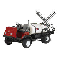
Toro Multi Pro 5700-D Service Manual (248 pages)
Brand:
Toro
| Category:
Lawn and Garden Equipment
| Size: 14 MB
Table of Contents
This Page Is Intentionally Blank.
3
Table of Contents
3
Safety
7
Chapter 1 -- Safety
8
Safety Instructions
8
Before Operating
8
While Operating
8
Maintenance and Service
9
Jacking Instructions
10
Safety and Instruction Decals
10
Product Records and Maintenance
11
Chapter 2 -- Product Records and Maintenance
11
Product Records
11
Equivalents and Conversions
12
Product Records
12
Torque Specifications
13
Fastener Identification
13
Standard Torque for Dry, Zinc Plated and Steel Fasteners (Inch Series Fasteners)
14
Standard Torque for Dry, Zinc Plated and Steel Fasteners (Metric Fasteners)
15
Conversion Factors
16
Other Torque Specifications
16
Maintenance
17
Chapter 3 -- Kubota Diesel Engine
19
Introduction
19
Chapter 5 -- Electrical System
20
Chapter 6 -- Spray System
20
Specifications
20
Service and Repairs
22
Chapter 4 - Hydraulic System)
31
Chapter 7 -- Chassis
31
Hydraulic System
35
Adjustments
35
Eaton Model 26000 Single Gear Pump Repair Information
35
Traction Circuit
43
Steering Circuit
44
Spray Pump Drive Circuit
45
Special Tools
46
Hydraulic Pressure Test Kit
46
Hydraulic Tester (Pressure and Flow)
46
Hydraulic Test Fitting Kit
47
Troubleshooting
48
Testing
50
Traction Circuit Charge Pressure Test
51
Traction Circuit Relief Pressure Test
52
Gear Pump Flow Test
53
Steering Circuit Relief Pressure Test
54
Steering Control Valve and Steering Cylinder Test
55
Spray Pump Drive Circuit Relief Pressure Test
56
Wheel Motor Efficiency: Case Drain Test
57
Pulse Width Modulated (PWM) Valve Flow Test
58
Adjustments
59
Adjust Traction Pedal for Neutral (Machines with Serial Numbers above 310000000)
59
Adjust Traction Pedal for Neutral (Machines with Serial Numbers below 310000000)
59
Adjust Relief Valve
60
Service and Repairs
61
General Precautions for Removing and Installing Hydraulic System Components
61
Check Hydraulic Lines and Hoses
61
Flush Hydraulic System
62
Charge Hydraulic System
63
Gear Pump
64
Gear Pump Service
66
Piston (Traction) Pump
68
Piston (Traction) Pump Service
70
Manual Servo Control Assembly
71
Wheel Motors
72
Wheel Motor Service
74
Spray Pump Drive Motor
76
Spray Pump Drive Motor Service
78
Relief Valve
79
Pulse Width Modulated (PWM) Valve
80
Steering Control Valve
82
Steering Control Valve Service
84
Steering Cylinder
86
Steering Cylinder Service
88
Oil Cooler
90
Hydraulic Reservoir
92
General Information
35
Hydraulic Flow Circuits
35
Hydraulic Schematic
35
Service and Repairs
35
Special Tools
35
Specifications
35
Testing
35
Troubleshooting
35
Electrical System
95
Electrical Diagrams
96
Special Tools
97
Multimeter
97
Battery Terminal Protector
97
Battery Hydrometer
97
Troubleshooting
98
Starting Problems
98
General Run Problems
99
Electrical System Quick Checks
100
Battery Test (Open Circuit Test)
100
Charging System Test
100
Neutral Switch Operation
100
Component Testing
101
Ignition Switch
101
Neutral Switch
102
Hour Meter
102
Headlight Switch
103
Cruise Control Switch
104
Cruise Control Coil
104
Brake Pedal Switch
105
Temperature Sender
106
Indicator Lights
107
Traction Speed Sensor
108
Accessory Solenoid
109
Pressure Rate and Boom Actuator Switches
110
Spray Pump, Agitation and Boom Control Switches
111
Master Boom (Foot) Switch
112
Pulse Width Modulated (PWM) Valve Solenoid
113
Manual Interface Module
114
Relays
115
Glow Relay
116
Fuel Stop Solenoid
117
Glow Controller
118
Fuel Pump
119
Fusible Link Harness
120
Diode Assembly
120
Service and Repairs
121
Headlights
121
Traction Speed Sensor
122
Cruise Control Coil
123
Battery Storage
124
Battery Care
124
Battery Service
125
Spray System
129
Specifications
130
General Information
131
Precautions Concerning Chemicals Used in Spray System
131
Precautions for Removing or Adjusting Spray System Components
131
O--Ring Seal Kit
131
Spray System Flow Diagram
132
Spray System Operation
133
Troubleshooting
134
Service and Repairs
136
Suction Dampener
136
Pressure Dampener
137
Spray Pump
138
Spray Pump Service
140
Agitation Nozzles (Tank Mounted)
144
Pressure Relief Valve (Tank Mounted)
146
Spray Control Assembly
148
Boom Valve Motor Assembly
150
Agitation Valve Motor Assembly
152
Boom and Agitation Valve Motor Service (Machines with Serial Numbers below 310000000)
154
Boom and Agitation Valve Motor Service (Machines with Serial Numbers above 310000000)
157
Boom Bypass
158
Tank Suction
160
Tank Drain Valve (Machines with Serial Numbers below 270000000)
162
Tank Drain Valve (Machines with Serial Numbers above 270000000)
164
Turret Bodies
166
Turret Body Service
167
Boom Frame Breakaway Pivot Assembly (Machines with Serial Numbers below 260000000)
168
Boom Hinge (Machines with Serial Numbers above 260000000)
170
Boom Actuator (Machines with Serial Numbers below 260000000)
172
Boom Actuator Service (Machines with Serial Numbers below 260000000)
174
Boom Actuator (Machines with Serial Numbers above 260000000)
176
Boom Actuator Service (Machines with Serial Numbers above 260000000)
178
Pro Control Spray System (Optional)
180
Chassis
181
Specifications
182
Service and Repairs
183
Tie Rod Ends
183
Front Wheels and Hubs
184
Spindles
186
Front Suspension
188
Brake Assembly
190
Brake Inspection and Repair
192
Brake Cables
193
Planetary Wheel Drive Assembly
194
Planetary Wheel Drive Service
196
.1 Sonic Boom System
199
General Information
200
Installation Instructions
200
Precautions Concerning Chemicals Used in Spray System
200
Precautions for Removing or Adjusting Spray System Components
200
Special Tools
201
Electrical Schematic
202
Sonic Boom System Operation
204
Sprayer Operation on Level Turf
205
Rise in Turf Encountered
209
Boom Level Changed by Operator During Automatic Operation
211
Manual Boom Operation
213
Troubleshooting
214
Sonic Boom Light
214
Diagnostic Display
215
Troubleshooting Chart
218
Service and Repairs
220
Sonic Mode Switch
220
Relays
221
Electronic Control Unit (ECU)
222
Sonic Sensor
223
Electrical Diagrams
225
Chapter 8
227
Vehicle Electrical Schematic
227
Spray System Electrical Schematic
228
Number above 260000000)
229
Spray System Electrical Schematic (Serial Number below 260000000)
228
Glow Plug Circuit
230
Start Circuit
231
Run Circuit
232
Cruise Control Circuit
233
Vehicle Wire Harness (Serial Number below 240000300)
234
Vehicle Wire Harness (Serial Number from 240000300 to 290999999)
235
Below 260000000)
240
From 260000001 to 270999999)
242
From 280000001 to 290999999)
244
Above 310000000)
246
Advertisement
Advertisement
Related Products
Toro ProCore
Toro Sand Pro 08706
Toro multi-pro 1200
Toro MultiPro 1200
Toro Multi Pro 5500
Toro Multi Pro 5800
Toro Sand Pro 5020
Toro Sand Pro 5040
Toro Multi Pro 5800-G
Toro Multi Pro 5800-D
Toro Categories
Lawn Mower
Lawn Mower Accessories
Snow Blower
Lawn and Garden Equipment
Utility Vehicle
More Toro Manuals
Login
Sign In
OR
Sign in with Facebook
Sign in with Google
Upload manual
Upload from disk
Upload from URL