Sign In
Upload
Manuals
Brands
Topcon Manuals
Measuring Instruments
GREEN LABEL GTS-255
Topcon GREEN LABEL GTS-255 Manuals
Manuals and User Guides for Topcon GREEN LABEL GTS-255. We have
1
Topcon GREEN LABEL GTS-255 manual available for free PDF download: Instruction Manual
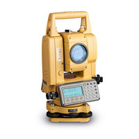
Topcon GREEN LABEL GTS-255 Instruction Manual (176 pages)
ELECTRONIC TOTAL STATION
Brand:
Topcon
| Category:
Measuring Instruments
| Size: 6 MB
Table of Contents
General Handling Precautions
3
Precautions for Safe Operation
4
User
6
Table of Contents
7
Nomenclature and Functions
10
Nomenclature
10
Display
12
Operating Key
13
Function Key (Soft Key)
14
Star Key Mode
15
Serial Signal RS-232C Connector
16
Preparation for Measurement
17
Setting Instrument up for Measurement
17
Power Switch Key on
18
Battery Power Remaining Display
19
Vertical and Horizontal Angle Tilt Correction
20
How to Enter Alphanumeric Characters
22
Angle Measurement
24
Measuring Horizontal Angle Right and Vertical Angle
24
Switching Horizontal Angle Right/Left
25
Measuring from the Required Horizontal Angle
25
Setting by Holding the Angle
25
Setting a Horizontal Angle from the Keys
26
Vertical Angle Percent Grade(%) Mode
26
Repetition Angle Measurement
27
Buzzer Sounding for Horizontal Angle 90° Increments
28
Compasses (Vertical Angle)
29
Distance Measurement
30
Setting of the Atmospheric Correction
30
Setting of the Correction for Prism Constant
30
Distance Measurement (Continuous Measurement)
30
Distance Measurement (N-Time Measurement/Single Measurement)
31
Fine Mode/Tracking Mode/Coarse Mode
32
Stake out (S.O)
33
Offset Measurement
34
Angle Offset
35
Distance Offset Measurement
37
Plane Offset Measurement
39
Column Offset Measurement
41
Coordinate Measurement
43
Setting Coordinate Values of Occupied Point
43
Setting Height of the Instrument
44
Setting Height of Target (Prism Height)
44
Execution of Coordinate Measuring
45
SPECIAL MODE (Menu Mode)
46
Application Measurement (PROGRAMS)
47
Remote Elevation Measurement (REM)
47
Missing Line Measurement (MLM)
50
Setting Z Coordinate of Occupied Point
53
Area Calculation
56
Point to Line Measurement
59
Setting the GRID FACTOR
61
Setting Illumination of Display and Cross Hairs
62
Setting Minimum Reading
63
Auto Power off
64
Vertical and Horizontal Angle Tilt Correction (Tilt ON/OFF)
64
Systematic Error of Instrument Correction
65
Heater ON/OFF
65
Setting RS-232C Communication with External Device
66
Setting Contrast of Display
67
Road
68
Input Start Point
69
Input Road Data
70
Search Data
74
Edit Data
74
Set OCC and BS
75
Setout Road
77
Select a File
78
Initialize ROAD Data
78
Data Collection
79
Preparation
81
Selecting a File for Data Collection
81
Selecting a Coordinate File for Data Collection
82
Occupied Point and Backsight Point
82
Operational Procedure of "DATA COLLECT
85
Data Collect Offset Measurement Mode
88
Angle Offset Measurement
88
Distance Offset Measurement
90
Plane Offset Measurement
92
Column Offset Measurement
94
NEZ Auto Calculation
95
Point to Line Measurement
96
To Change to the Point to Line Measurement
96
Executing a Point to Line Measurement
97
Editing PCODE Library [PCODE INPUT]
98
Setting Parameter of Data Collect [CONFIG.]
99
Layout
100
Preparation
102
Setting the GRID FACTOR
102
Selecting Coordinate Data File
103
Setting Occupied Point
104
Setting Backsight Point
105
Executing a Layout
107
Layout of Coordinates of Point to Line
109
Setting a New Point
110
Side Shot Method
110
Resection Method
112
Memory Manager Mode
116
Display Internal Memory Status
117
Searching Data
118
Measured Data Searching
118
Coordinate Data Searching
120
PCODE LIBRARY Searching
121
File Maintenance
122
Rename a File
123
Searching Data in a File
123
Deleting a File
124
Coordinate Data Direct Key Input
125
Coordinate Data Input
125
PTL (Point to Line) Data Input
126
Delete a Coordinate Data from a File
127
Editing PCODE Library
128
Data Communications
129
Sending Data
129
Loading Data
130
Setting Parameter of Data Communications
131
Initialization
132
Set Audio Mode
133
Setting the Prism Constant Value
134
Setting Atmospheric Correction
135
Calculation of Atmospheric Correction
135
Setting of Atmospheric Correction Value
135
Correction for Refraction and Earth Curvature
140
Distance Calculation Formula
140
Power Source and Charging
141
On-Board Battery BT-G1W
141
Detach/Attach of Tribrach
143
Selecting Mode
144
Items of the Selecting Mode
144
How to Set Selecting Mode
146
Check and Adjustment
148
Checking and Adjusting of Instrument Constant
148
Checking the Optical Axis
149
Checking/Adjusting the Theodolite Functions
150
Checking/Adjusting the Plate Level
151
Checking/Adjusting the Circular Level
151
Adjustment of the Vertical Cross-Hair
152
Collimation of the Instrument
153
Checking/Adjusting the Optical Plummet Telescope
154
Adjustment of Vertical Angle 0 Datum
155
How to Set the Instrument Constant Value
156
Adjustment of Compensation Systematic Error of Instrument
157
Reference Frequency Check Mode
159
Precautions
160
Special Accessories
161
Battery System
162
Prism System
163
Error Displays
164
Specifications
166
Regulations
169
Appendix
172
Dual Axis Compensation
172
Precaution When Charging or Storing Batteries
174
Advertisement
Advertisement
Related Products
Topcon GREEN LABEL GTS-250 Series
Topcon GREEN LABEL GTS-252
Topcon GTS-236N
Topcon GTS-239N
Topcon GTS-233W
Topcon GTS-235W
Topcon GTS-236W
Topcon GTS-230 Series
Topcon GTS-233
Topcon GTS-236
Topcon Categories
Measuring Instruments
Medical Equipment
Receiver
Laser Level
Controller
More Topcon Manuals
Login
Sign In
OR
Sign in with Facebook
Sign in with Google
Upload manual
Upload from disk
Upload from URL