Sign In
Upload
Manuals
Brands
Topcon Manuals
Measuring Instruments
GTS-239N
Topcon GTS-239N Manuals
Manuals and User Guides for Topcon GTS-239N. We have
1
Topcon GTS-239N manual available for free PDF download: Instruction Manual
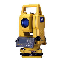
Topcon GTS-239N Instruction Manual (184 pages)
Electronic total station GTS-230N series
Brand:
Topcon
| Category:
Measuring Instruments
| Size: 5 MB
Table of Contents
Display for Safe Use
5
Safety Cautions
5
User
6
Exceptions from Responsibility
6
Safety Standard for Laser Beam
7
Symbol Mark While the Laser Is Emitting
7
Table of Contents
8
Standard Set Composition
11
1 Nomenclature and Functions
12
Nomenclature
12
Display
14
Operating Key
15
Function Key (Soft Key)
16
Star Key Mode
17
Serial Signal RS-232C Connector
19
Laser Plummet ON/OFF (Only for Laser Plummet Type)
20
2 Preparation for Measurement
21
Power Connection
21
Setting Instrument up for Measurement
22
Power Switch Key on
23
Battery Power Remaining Display
24
Vertical and Horizontal Angle Tilt Correction
25
How to Enter Alphanumeric Characters
27
3 Angle Measurement
29
Measuring Horizontal Angle Right and Vertical Angle
29
Switching Horizontal Angle Right/Left
30
Measuring from the Required Horizontal Angle
30
Setting by Holding the Angle
30
Setting a Horizontal Angle from the Keys
31
Vertical Angle Percent Grade (%) Mode
31
Repetition Angle Measurement
32
Buzzer Sounding for Horizontal Angle 90° Increments
33
Compasses (Vertical Angle)
34
4 Distance Measurement
35
Setting of the Atmospheric Correction
35
Setting of the Correction for Prism Constant
35
Distance Measurement (Continuous Measurement)
35
Distance Measurement (N-Time Measurement/Single Measurement)
36
Fine Mode/Tracking Mode/Coarse Mode
37
Stake out (S.O)
38
Offset Measurement
39
Angle Offset
40
Distance Offset Measurement
42
Plane Offset Measurement
44
Column Offset Measurement
46
5 Coordinate Measurement
48
Setting Coordinate Values of Occupied Point
48
Setting Height of the Instrument
49
Setting Height of Target (Prism Height)
49
Execution of Coordinate Measuring
50
6 SPECIAL MODE (Menu Mode)
51
Application Measurement (PROGRAMS)
52
Remote Elevation Measurement (REM)
52
Missing Line Measurement (MLM)
55
Setting Z Coordinate of Occupied Point
58
Area Calculation
61
Point to Line Measurement
64
Setting the GRID FACTOR
66
Setting Illumination of Display and Cross Hairs
67
Setting Mode 1
68
Setting Minimum Reading
68
Auto Power off
69
Vertical and Horizontal Angle Tilt Correction (Tilt ON/OFF)
69
Systematic Error of Instrument Correction (Only for GTS-233N/235N/236N)
70
Selecting Battery Type
70
Heater ON/OFF
71
Setting RS-232C Communication with External Device
72
Setting Contrast of Display
73
Road
74
Input Start Point
75
Input Road Data
76
Search Data
80
Edit Data
80
Set OCC and BS
81
Setout Road
83
Select a File
84
Initialize ROAD Data
84
7 Data Collection
85
Preparation
87
Selecting a File for Data Collection
87
Selecting a Coordinate File for Data Collection
88
Occupied Point and Backsight Point
88
Operational Procedure of "DATA COLLECT
91
Data Collect Offset Measurement Mode
94
Angle Offset Measurement
94
Distance Offset Measurement
96
Plane Offset Measurement
98
Column Offset Measurement
100
NEZ Auto Calculation
101
Point to Line Measurement
102
To Change to the Point to Line Measurement
102
Executing a Point to Line Measurement
103
Editing PCODE Library [PCODE INPUT]
104
Setting Parameter of Data Collect [CONFIG.]
105
8 Layout
106
Preparation
108
Setting the GRID FACTOR
108
Selecting Coordinate Data File
109
Setting Occupied Point
110
Setting Backsight Point
111
Executing a Layout
113
Layout of Coordinates of Point to Line
115
Setting a New Point
116
Side Shot Method
116
Resection Method
118
9 Memory Manager Mode
122
Display Internal Memory Status
123
Searching Data
124
Measured Data Searching
124
Coordinate Data Searching
126
PCODE LIBRARY Searching
127
File Maintenance
128
Rename a File
129
Searching Data in a File
129
Deleting a File
130
Coordinate Data Direct Key Input
131
Coordinate Data Input
131
PTL (Point to Line) Data Input
132
Delete a Coordinate Data from a File
133
Editing PCODE Library
134
Data Communications
135
Sending Data
135
Loading Data
136
Setting Parameter of Data Communications
137
Initialization
138
10 Set Audio Mode
139
11 Setting the Prism Constant Value
140
12 Setting Atmospheric Correction
141
Calculation of Atmospheric Correction
141
Setting of Atmospheric Correction Value
141
13 Correction for Refraction and Earth Curvature
146
Distance Calculation Formula
146
14 Power Source and Charging
147
On-Board Battery BT-52QA
147
15 Detach/Attach of Tribrach
149
16 Selecting Mode
150
Items of the Selecting Mode
150
How to Set Selecting Mode
152
17 Check and Adjustment
154
Checking and Adjusting of Instrument Constant
154
Checking the Optical Axis
155
Checking/Adjusting the Theodolite Functions
156
Checking /Adjusting the Plate Level
157
Checking /Adjusting the Circular Level
157
Adjustment of the Vertical Cross-Hair
158
Collimation of the Instrument
159
Checking / Adjusting the Optical Plummet Telescope
160
Adjustment of Vertical Angle 0 Datum
161
Checking / Adjusting the Laser Plummet (for Laser Plummet Type)
162
How to Set the Instrument Constant Value
163
Adjustment of Compensation Systematic Error of Instrument
164
Reference Frequency Check Mode
166
18 Precautions
167
19 Special Accessories
168
20 Battery System
171
21 Prism System
172
22 Error Displays
173
23 Specifications
175
Appendix
178
Dual Axis Compensation
178
Precaution When Charging or Storing Batteries
180
Advertisement
Advertisement
Related Products
Topcon GTS-239W
Topcon GTS-239
Topcon GTS-230N
Topcon GTS-233N
Topcon GTS-236N
Topcon GTS-230W Series
Topcon GTS-235W
Topcon GTS-236W
Topcon GTS-230 Series
Topcon GTS-235
Topcon Categories
Measuring Instruments
Medical Equipment
Receiver
Laser Level
Controller
More Topcon Manuals
Login
Sign In
OR
Sign in with Facebook
Sign in with Google
Upload manual
Upload from disk
Upload from URL