Sign In
Upload
Manuals
Brands
Tokyo Sokki Kenkyujo Manuals
Data Loggers
TC-32K
Tokyo Sokki Kenkyujo TC-32K Manuals
Manuals and User Guides for Tokyo Sokki Kenkyujo TC-32K. We have
1
Tokyo Sokki Kenkyujo TC-32K manual available for free PDF download: Operation Manual
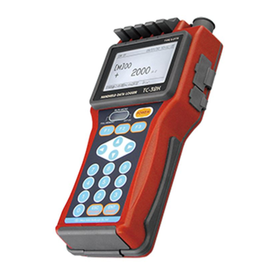
Tokyo Sokki Kenkyujo TC-32K Operation Manual (133 pages)
Brand:
Tokyo Sokki Kenkyujo
| Category:
Data Loggers
| Size: 5 MB
Table of Contents
Table of Contents
4
Chapter 1 Overview
9
Features
10
Overview
10
Details about each Part
11
Front and Side
11
Top, Bottom, and Back
12
Chapter 2 Preparation
13
Instructions for Use
14
Power Source
15
How to Set Batteries
15
Operating Time by Batteries
16
Connection for AC Adapter
17
Power ON/OFF
17
Instructions for Field Measurement
18
Grounding
18
Lightning Protection
18
Screen Outline
19
Startup Screen
19
Screen Configuration
19
Operation Outline
20
Operation System
20
Key Switch
21
Key Lock
21
Sensor Connection
24
How to Use Input Terminal Block
24
Wire Connection by Sensor Type
25
Chapter 4 Monitor Display and Measurement
27
Monitor Display
28
Value Monitor
28
Waveform Monitor
29
Meaning of Displayed Value
29
Monitor Type Selection
30
Waveform Monitor Setting
30
Monitor Screen Outline
28
Initial Value Processing
31
Initial-In
31
Initial-In of Monitor Channel
32
Rewrite of Initial Value
33
Channel Setting
34
Measurement Mode
34
Switching of Measurement Mode
34
Channel Setting in Single Channel Mode
35
Record of Measurement Value
36
Manual Measurement
36
Record of Measurement Values
36
Auto Measurement
37
Sub LCD
37
Chapter 5 Measurement Setting
38
Measurement Setting Outline
39
Sensor Mode
40
Sensor Mode Setting
41
Group Setting
42
Coefficient, Indication Digits, and Unit
43
Parameters
43
Parameter Setting Example
43
Coefficient, Indication Digits, and Unit Setting
44
Coefficient Setting by Cap/Ro
46
Check of Coefficient
47
Thermocouple RJC Setting
48
TEDS Sensor
49
Reading of Sensor Setting
49
Applying the Read Setting
50
Switching of Measurement Mode
50
Switching between Measure and Direct
51
Automatic Measurement
52
Interval Measurement
52
Interval Timer Setting
52
Automatic Measurement
53
Real-Time Start Setting
54
Goto Step
55
Goto Step Setting
56
Start and Stop of Interval Measurement
57
Sleep Function
58
Various Checks
59
Insulation Check
59
Resistance Check
59
Dispersion Check
60
Lead Wire Resistance Check
60
Bridge Output Check
60
Coefficient Setting Check
61
Measurement Auxiliary Setting
61
Simple Measure Setting
61
Comet Setting
63
Power Source Frequency of Measurement Environment
63
Initial-In Permission
64
Burnout Check Setting
64
Chapter 6 Record Setting
66
Record Setting Outline
67
Data Memory
68
Data Memory Structure
68
Readout of Data
69
Data Memory Setting
69
Deletion of Data in Data Memory
70
Printout of Data Memory
70
CF Card
71
Readout of Data
71
File Name and File Format Setting
72
File Deletion
74
Saving Data File
74
Reading of Setting File
75
CF Card Formatting
75
File Copy
76
Recording in Data Memory and CF Card
77
Chapter 7 Interface Setting
79
Interface Setting Outline
80
RS-232C Setting
81
Communication Conditions
81
Data Output
82
Connection with Device
82
Data Output Destination and Output Procedure
82
Data Output Format Setting
83
Cautions for Printer Setting
84
External Indicator Setting
84
Remote Measurement
85
Configuration
85
Function
85
Chapter 8 Other Settings
87
Other Setting Outline
88
Other Settings Outline
88
Auto Power-Off Setting
89
Date and Time Setting
90
Version Information
90
Switching between Japanese and English
91
Switching between Japanese/English
91
Maintenance
92
LCD Backlight Setting
92
LCD Backlight Brightness
93
Contrast Setting
93
Buzzer Volume Setting
94
Upgrading
94
Factory Setting
96
Execution of Factory Setting
96
Factory Shipment Setting
96
List of Factory Setting
97
Chapter 9 Increase of the Number of Measurement Points
99
Outline of Increase of the Number of Measurement Points
100
Options to Increase the Number of Measurement Points
100
Switching Box
101
CSW-5B Connection
101
Data Memory
101
Measurement Mode Setting
102
Channel Setting
102
Box Number Setting
102
Monitor Display
103
Monitor Type Selection
103
Initial Value Processing
104
Program Setting
104
Record of Measurement Value
105
Various Checks
105
Inclinometer Adapter
106
Connection
106
Data Memory
106
Measurement Mode Setting
107
Channel Setting
107
Monitor Display
107
Program Setting
108
Record of Measurement Value
108
Unavailable Function in Inclinometer Mode
109
Chapter 10 Strain Compensation
110
Wire Connection of Strain Gauge
111
1-Gauge 4-Wire Method
111
Quarter Bridge 2-Wire Method
111
Quarter Bridge 3-Wire Method
111
Half Bridge Method
111
Full Bridge Method
111
Sensitivity Drop Due to Sensor Cable Extension
112
Measurement by Constant Voltage Method
112
Measurement by Constant Current Method
114
Complete Compensation Method
116
Of Strain (Comet)
116
Comet NON
117
Comet a
117
Comet B (Quarter Bridge 3-Wire Method Only)
117
Complete Compensation Method of Strain (Comet)
116
Compensation Method in Quarter Bridge 3-Wire Method
116
How to Find the Lead Wire Resistance
118
Compensation Method in 1-Gauge 4-Wire Method
119
Chapter 11 Specifications
121
Specifications
121
Standard Accessories
125
1-Gauge 4-Wire Method
126
Outside Drawing
127
Advertisement
Advertisement
Related Products
Tokyo Sokki Kenkyujo Categories
Data Loggers
More Tokyo Sokki Kenkyujo Manuals
Login
Sign In
OR
Sign in with Facebook
Sign in with Google
Upload manual
Upload from disk
Upload from URL