Table of Contents
Advertisement
Quick Links
Advertisement
Chapters
Table of Contents

Summary of Contents for Tokyo Sokki Kenkyujo TC-32K
- Page 1 O p e r a t i o n M a n u a l HANDHELD TC-32K DATA LOGGER...
- Page 2 NOTICE This manual describes how to operate Handheld Data Logger TC-32K and its operation procedures. Please read this operation manual thoroughly to familiarize yourself with the functions and operating procedures of this product. It will enable you to make maximum use of all its functions and take precise measurements effectively.
- Page 3 The system is vulnerable to the dielectric effect of thunderbolts. Take Caution preventive measures against thunderbolts where applicable. Contact your dealer or Tokyo Sokki Kenkyujo for details. Do not forcibly drag the system with connection cables connected. cables may be damaged and/or the connectors may be disconnected. In Caution addition, do not apply impact to the connector of the cable.
-
Page 4: Table Of Contents
Table of Contents NOTICE Safety Precautions Table of Contents Chapter 1 Overview 1.1 Overview ································································································ 1 - 2 1.2 Features ································································································· 1 - 2 1.3 Details about each part ············································································· 1 - 3 Front and side ·················································································· 1 - 3 Top, bottom, and back ········································································... - Page 5 Measurement mode ········································································· 4 - 8 Switching of measurement mode ························································ 4 - 8 Channel setting in single channel mode ················································· 4 - 9 4.5 Record of measurement value ··································································· 4 -10 Manual measurement ······································································· 4 -10 Auto measurement ··········································································· 4 -11 4.6 Sub LCD ·······························································································...
- Page 6 Chapter 6 Record Setting 6.1 Record setting outline ··············································································· 6 - 2 6.2 Data memory ·························································································· 6 - 3 Data memory structure ······································································· 6 - 3 Readout of data ················································································ 6 - 4 Data memory setting ·········································································· 6 - 4 Deletion of data in data memory ···························································...
- Page 7 Chapter 9 Increase of the Number of Measurement Points 9.1 Outline of increase of the number of measurement points ································ 9 - 2 Options to increase the number of measurement points ···························· 9 - 2 9.2 Switching box ·························································································· 9 - 3 CSW-5B connection ··········································································...
- Page 8 Chapter 12 Error Message 12.1 Explanations and countermeasures for error messages ································ 12 - 2...
-
Page 9: Chapter 1 Overview
Chapter Overview 1.1 Overview ···················································· 1 - 2 1.2 Features ···················································· 1 - 2 1.3 Details about each part ·································· 1 - 3... -
Page 10: Overview
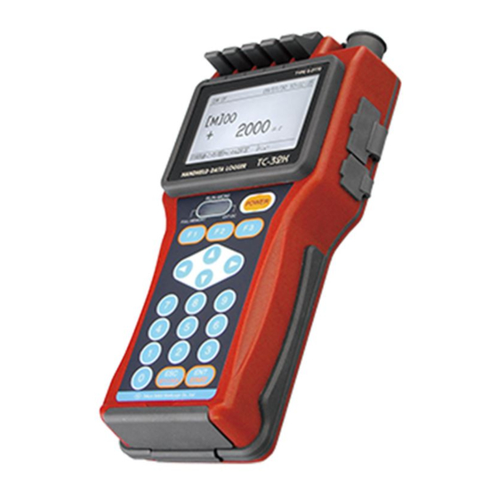
1.1 Overview 1.1 Overview TC-32K is a compact hand held instrument that you can hold with one hand. Its splash proof construction allows safety use outside. The terminals connecting the sensors are one-touch type, and provide easy connection with the lead wires and banana plugs, and speedy measurement. You can set the sensor mode, coefficient, and initial values of up to 20 channels and record their data, so it is easy to organize the data even when you are moving around multiple fields to collect data. -
Page 11: Details About Each Part
1.3 Details about each part 1.3 Details about each part ■ Front and side Input terminal Connects strain gauges and various sensors. Main LCD Displays monitored measurement values and provides various settings. Sub LCD Displays the timer operation and memory status. POWER key Main power switch Function key... -
Page 12: Top, Bottom, And Back
1.3 Details about each part ■ Top, bottom, and back Wire connection label Shows how to connect wires of strain gauges. Input connector NDIS connector receptacle for connecting strain gauge type transducer CF card slot Slot for memory card based on CF card TYPE I Eject button Double-push button to remove a CF card CF cover... - Page 13 Chapter Preparation 2.1 Instructions for use ······································· 2 - 2 2.2 Power source ·············································· 2 - 3 2.3 Instructions for field measurement ··················· 2 - 6 2.4 Screen outline ············································· 2 - 7 2.5 Operation outline ·········································· 2 - 8...
-
Page 14: Instructions For Use
2.1 Instructions for use 2.1 Instructions for use Please pay attention to the following information when using this instrument. With the connector capped, this instrument is equivalent to IP-54 (not affected by Warning water splash from any direction). Do not let the instrument soak directly in water. For waterproof, the connector cap and the CF cover must be attached correctly. -
Page 15: Power Source
2.2 Power source 2.2 Power source This instrument is driven by four AA size batteries or an optional AC adapter. ■ How to set batteries You can use size AA alkaline batteries or rechargeable batteries for this instrument. This instrument does not have function to charge the batteries set inside. -
Page 16: Operating Time By Batteries
Operating time by batteries varies depending on ambient temperature and other factors. The list below shows standard operating time when using new alkaline batteries. Operating time in continuous use Alkaline battery Condition Single unit of TC-32K 10 hours TC-32K + CSW-5A or 6 hours CSW-5B The operating time above is on the following conditions. -
Page 17: Connection For Ac Adapter
Then, connect the AC adapter unit to the 100~240 V AC CR-1869 wall socket. Even if batteries are set in the TC-32K, power supply from the AC adapter is prioritized. To AC100~240V wall socket ▪ Do not use any AC adapter other than “CR-1869.”. -
Page 18: Instructions For Field Measurement
NZ-6B is the 6-wire system arrester for strain gauge type transducers and also applied to strain gauges. Insert the arrester near the sensor as much as possible. Although the input terminals of TC-32K have simple built-in arresters for sensor, it is recommended to install another arrester for sensor together to... -
Page 19: Screen Outline
2.4 Screen outline 2.4 Screen outline ■ Startup screen Soon after you turn on power, the startup screen shown in the left appears. Then, the monitor screen shown below appears. ■ Screen configuration You can move to the setting screen for functions and measurement operations from the monitor screen that appears after startup. -
Page 20: Operation Outline
From the monitor screen, you can move to various modes with three function keys. This section explains these function keys and systems, and the keys used for operation and their functions. ■ Operation system The operation system of TC-32K is shown below: Monitor screen Process of Initial value... -
Page 21: Key Switch
2.5 Operation outline ■ Key switch Commencing with operation to move to Menu, you can operate the TC-32K with the key switches located on the front to switch the screens, input values, start measurement, and perform checking. This document describes key switches to be operated, as “Select [F3]”, to explain the procedures. The... - Page 22 2.5 Operation outline ✎memo 2-10...
- Page 23 Chapter Sensor Connection 3.1 Sensor connection ····································· 3 - 2...
-
Page 24: Sensor Connection
3.1 Sensor connection 3.1 Sensor connection Two ways of connection are available; with the one-touch terminal block, or with the NDIS connector. The one-touch terminal block system is applied to sensor cables without connector, and also applicable to a wide range of cables including thin wires, and wires with crimp terminals or banana plugs. ■... -
Page 25: Wire Connection By Sensor Type
3.1 Sensor connection ■ Wire connection by sensor type Wire connection procedure varies according to type of the sensor to be measured. The table below shows the connection procedure and the proper sensor mode for each sensor. ○ Wire connection table Measurement Wire connection diagram Sensor mode... - Page 26 3.1 Sensor connection Measurement Wire connection diagram Sensor mode object Transducer 4GAGE 4G C350Ω with NDIS connector plug 4G 0-2V Green Black Transducer 4GAGE White 4G C350Ω without connector 4G 0-2V For most of our transducers Thermocouple Thermocouple ̶ temperature T, K, J, B measurement S, R, E, N...
- Page 27 Chapter Monitor Display and Measurement 4.1 Monitor screen outline ························· 4 - 2 4.2 Monitor display ·································· 4 - 2 4.3 Initial value processing ························ 4 - 5 4.4 Channel setting ·································· 4 - 8 4.5 Record of measurement values ············ 4 -10 4.6 Sub LCD ··········································...
-
Page 28: Monitor Screen Outline
4.1 Monitor screen outline 4.1 Monitor screen outline After power-on, the monitor screen appears on the display. This screen displays measurement values (monitored values), time, status, and other information. You can change the screen to set other various functions using key switches. Communicating with RS-232C Communicating with USB Saving in CF card... -
Page 29: Waveform Monitor
4.2 Monitor display ○ Example of 5-channel display (multi-channel mode) Box number CSW-5B channel Mark showing that the channel is monitored ■ Waveform monitor The screen displays a line chart showing variation of measurement value with time. The number of channel that can be displayed in the waveform monitor is one. Monitored channel Measurement value (monitored value) -
Page 30: Monitor Type Selection
Select the display format of monitored value among value monitor, waveform monitor, and OFF. When you select “Monitor OFF”, the TC-32K does not supply bridge excitation to the sensor and does not display monitored value on the screen (it does not measure). -
Page 31: Initial Value Processing
4.3 Initial value processing 4.3 Initial value processing “Initial-in” is a function to memorize current measurement value as “initial value” in the TC-32K. It is used to subtract the initial value (initial unbalance value) of the strain gauge or strain gauge type transducer from measurement values for display. -
Page 32: Initial-In Of Monitor Channel
4.3 Initial value processing ■ Initial-in of monitor channel When a switching box CSW-5A (former model of CSW-5B) is connected, you can execute initial-in measurement only for the monitor channel in multi-channel mode. 1. Press [F1] key on the monitor screen to go to “Processing of initial value”. -
Page 33: Rewrite Of Initial Value
4.3 Initial value processing ■ Rewrite of initial value You can change initial value as you want, independently of the initial unbalanced value that the sensor has. 1. Press [F1] key on the monitor screen to go to “Processing of initial value”. 2. -
Page 34: Channel Setting
Select this mode when you connect one sensor to the terminal block or the NDI connector receptacle of the TC-32K. Parameters and initial values for up to 20 channels can be set and saved in the TC-32K from channel 00 to channel 19. -
Page 35: Channel Setting In Single Channel Mode
4.4 Channel setting 2. Channel setting screen corresponding to current measurement mode displayed. Press [F3] key to go to “Measurement mode switching”. 3. Move the cursor with [▲][▼] keys, and select a mode. 4. Press [ENT] key. The channel setting screen for the selected mode is displayed. -
Page 36: Record Of Measurement Value
4.5 Record of measurement value 4.5 Record of measurement value The TC-32K does not record measurement values when it is merely monitoring the value. record measurement values, press [ENT/START] key on the front panel for manual measurement, or select auto measurement (interval measurement) function which allows automatic data saving. -
Page 37: Auto Measurement
4.6 Sub LCD ■ Auto measurement Measurement data on the monitor display are saved into the data memory or CF card at the set interval or the set time. For details about setting and start/stop operation of interval measurement, refer to “5.8: Auto measurement”. 4.6 Sub LCD The sub LCD lights up when the battery voltage goes down, the auto measurement function is running, no capacity remains in the data memory, or the AC adapter is used. - Page 38 Chapter Measurement Setting 5.1 Measurement setting outline ················· 5 - 2 5.2 Sensor mode ······································· 5 - 3 5.3 Coefficient, indication digits, and unit ···· 5 - 6 5.4 Thermocouple RJC setting ··················· 5 -11 5.5 TEDS sensor ····································· 5 -12 5.6 Switching of measurement mode ·········...
-
Page 39: Measurement Setting Outline
5.1 Measurement setting outline 5.1 Measurement setting outline This chapter explains operations and settings related to measurement, such as detailed setting of sensors, automatic measurement, and various checks. The configuration of these setting screens is shown below. Press [F3] key to go to the Menu screen. Move the cursor (reversed indication) with [▲][▼] keys and press [ENT] key, or enter the number using ten keys, to move to the setting screen you want to go. -
Page 40: Sensor Mode
Pt-RTD Pt-RTD measurement Digital linearized (Platinum resist- Pt100 3W ance temperature 3-wire method JIS C1604-1997 Pt100 detector) *1: When used in region of power source frequency 50Hz *2: This mode is available only for 1-channel measurement using TC-32K main unit. -
Page 41: Sensor Mode Setting
5.2 Sensor mode ■ Sensor mode setting 1. Move the cursor (reversed indication) with [▲][▼] keys on the Menu screen and press [ENT] key, or press [1] of ten keys, to go to “Program”. 2. Move the cursor (reversed indication) with [▲][▼] keys and press [ENT] key, or press [1] of ten keys, to go to “Sensor mode”. -
Page 42: Group Setting
5.2 Sensor mode ■ Group setting You can set a sensor mode and other settings mentioned later for multiple channels at once. This procedure is called “group setting”. Several channels from a certain channel to another channel are handled as one group. 1. -
Page 43: Coefficient, Indication Digits, And Unit
5.3 Coefficient, indication digits, and unit 5.3 Coefficient, indication digits, and unit ■ Parameters In order to measure physical quantities such as stress, load, displacement or pressure using strain gauges or strain gauge type transducers, and to display the measured values in physical unit, setting of the parameters shown below (coefficient, unit, and indication digits) is necessary. -
Page 44: Coefficient, Indication Digits, And Unit Setting
5.3 Coefficient, indication digits, and unit ○ When measuring a strain gauge type load cell in direct reading of physical value: In case of load cell with capacity of 5 kN and rated output of 2 mV/V For a load cell whose rated output is expressed in mV/V, calculate the strain using: 1 mV/V = 2000×10 Accordingly, strain is calculated as 2mV/V×2000 = 4000×10 for this example. - Page 45 5.3 Coefficient, indication digits, and unit 2. Parameters for each channel are indicated. Move the cursor with [▲][▼][◄][►] keys to the item you want to change, and press [ENT] key. With [F3] key, you can go to “Group setting”. ○ Setting coefficient Enter values directly with ten keys.
-
Page 46: Coefficient Setting By Cap/Ro
■ Coefficient setting by Cap/RO On the test data sheet attached to a transducer, capacity (Cap) and rated output (RO) are shown. Coefficient setting can also be done by inputting these Cap and RO, and unit. 1. On the “Coefficient, Digit, Unit” screen, move the cursor to the coefficient of the channel for which Cap/RO is entered, and press [F2] key. -
Page 47: Check Of Coefficient
3. After setting all items, press [ESC] key. The screen shown in the left appears. Move the cursor to [Ok] and press [ENT] key. The setting is applied, and the display returns to “Coefficient, Digit, Unit” screen. ○ Example of coefficient setting by Cap/RO This is an example of setting a load cell with capacity (Cap) of 5kN and rated output (RO) of 2mV/V. -
Page 48: Thermocouple Rjc Setting
3. Move the cursor to either “Internal (junction)” or “External (junction)” with [◄][►] keys, and press [ENT] key. ✍ The TC-32K has a built-in temperature sensor inside. This temperature sensor works as a reference junction in thermocouple measurement when linearizing the output of the thermocouple. -
Page 49: Teds Sensor
Indication Detail -------- Timeout (communication error) ******** TEDS sensor which is not supported by TC-32K No change Sensor which is not TEDS compatible, or not connected ○ This reading function is available only for TEDS compatible sensors Note having NDIS connectors. -
Page 50: Applying The Read Setting
5.6 Switching of measurement mode ■ Applying the read setting 1. Execute “Reading of TEDS sensor”. 2. To apply the read setting, press [F2] key. 3. Move the cursor to “Ok” with [◄][►] keys, and press [ENT] key. The read setting reflected (applied) -
Page 51: Switching Between Measure And Direct
5.7 Switching between Measure and Direct 5.7 Switching between Measure and Direct There are two ways to display measurement values: “Measure value” from which the initial value is subtracted ([M] or [m] is indicated on the monitor), and “Direct value” from which the initial value is not subtracted ([D] is indicated on the monitor). -
Page 52: Automatic Measurement
5.8 Automatic measurement 5.8 Automatic measurement This function allows recording of measurement data at the set time or set interval. ■ Interval measurement “Interval measurement” is a function to measure and record data automatically at a regular interval called “interval time”. This section explains outline of this function by the case where the program consists of three steps and each step is repeated twice. -
Page 53: Automatic Measurement
5.8 Automatic measurement 2. Move the cursor (reversed indication) with [▲][▼] keys on the Menu screen and press [ENT] key, or press [1] of ten keys, to go to “Interval measurement”. 3. Move the cursor (reversed indication) to the step to be set with [▲][▼] keys, and press [ENT] key or [F1] key. -
Page 54: Real-Time Start Setting
5.8 Automatic measurement 8. Then, set “End of interval” for Step 02 with the similar procedure. Now, the setting of interval measurement completes. ✍ Without setting of the step of “End of interval”, measurement is possible. 9. During interval measurement, you can see the setting of interval measurement by “Interval measurement”... -
Page 55: Goto Step
Goto Step is the function to move to a specified step. You can use this function to repeat interval measurement. For example, when you set as the table below, TC-32K executes interval measurement for Step 01 to Step 02, and then executes similar steps again. Step... -
Page 56: Goto Step Setting
5.8 Automatic measurement The actual interval measurement timing is as follows: Start ↓ Measurement point by step ┗━┻━━┻━━┻━━┻━┻━━┻━━┻━━┻--------- Interval time (hour) ■ Goto Step setting 1. Go to “Interval measurement”. Move the cursor (reversed indication) to the step to be set with [▲][▼] keys, and press [ENT] key. -
Page 57: Start And Stop Of Interval Measurement
“Sleep Off” with [◄][►] keys, and press [ENT] key. The “Sleep” is a function to turn off ✍ the power of the TC-32K when it is not measuring so as to reduce power consumption. However, function does not work in a step with interval of less than 1 minute. -
Page 58: Sleep Function
After completing the measurement at the starting time, the TC-32K goes into sleep status (the indicator of sub LCD lights up), and the display blacks out. Operation sequence of interval measurement with sleep function is shown in the illustration below. -
Page 59: Various Checks
This is a function to check insulation resistance between the sensor connected to the input terminal and the test specimen. To enable this check, the input terminal E of the TC-32K must be connected to the test specimen with a ground wire or an equivalent. -
Page 60: Dispersion Check
5.9 Various checks ■ Dispersion check This is a function to repeat measurement 10 times and output difference between the maximum value and the minimum value as “Dispersion”. 1. Move the cursor (reversed indication) to “Dispersion check” with [▲][▼] keys on the “Various check”... -
Page 61: Coefficient Setting Check
■ Coefficient setting check This function is used to check whether the set coefficient for a monitor channel is appropriate based on the relation between the input value and the displayed value. 1. Move the cursor (reversed indication) to “Coefficient check” with [▲][▼] keys on the “Various check”... - Page 62 5.10 Measurement auxiliary setting 3. Move the cursor (reversed indication) to “Simple measure” with [▲][▼] keys and press [ENT] key. 4. The Simple measure mark appears. the same time, the measurement object corresponding to the sensor mode (in the case shown left, it is “Strain”) is displayed.
-
Page 63: Comet Setting
Comet, you can acquire more accurate strain value. ■ Power source frequency of measurement environment Set a commercial power source frequency of the region where you are using the TC-32K. This setting may prevent variation or shift when the measurement value is unstable. -
Page 64: Initial-In Permission
5.10 Measurement auxiliary setting ■ Initial-in permission You can prohibit initial-in operation by this function. It is useful to prevent unnecessary initial-in operation during long term measurement or the like. 1. Move the cursor (reversed indication) with [▲][▼] keys on the “Setting concerning measurement”... - Page 65 5.10 Measurement auxiliary setting ✎memo 5-28...
- Page 66 Chapter Record Setting 6.1 Record setting outline ························· 6 - 2 6.2 Data memory ····································· 6 - 3 6.3 CF card ·············································· 6 - 6 6.4 File copy ·········································· 6 -11 6.5 Recording in data memory and CF card 6 -12...
-
Page 67: Record Setting Outline
6.1 Record setting outline 6.1 Record setting outline This chapter explains operations and settings related to data management, such as readout and copy of data from the internal data memory and CF card. The configuration of these operations and setting screens are shown below: Move the cursor (reversed indication) with [▲][▼] Press [F3] key to go to the Menu screen. -
Page 68: Data Memory
6.2 Data memory 6.2 Data memory This section explains the structure of the data memory, readout and deletion of data from the internal memory, and data number setting. ■ Data memory structure With the single channel mode, up to 80,000 data can be stored. The data memory consists of one area, and stores data in the measurement order sequentially. -
Page 69: Readout Of Data
6.2 Data memory ■ Readout of data 1. Move the cursor (reversed indication) with [▲][▼] keys on the Data memory screen and press [ENT] key, or press [1] of ten keys, to go to “File dump”. 2. Data of the number where the cursor is located are displayed. -
Page 70: Deletion Of Data In Data Memory
6.2 Data memory ○ Ring buffer setting Move the cursor with [◄][►] keys and select either “Off” or “On”. ○ Repeated measurement with ring buffer ON When the data memory capacity is fully occupied and recording of data is in the second cycle or later, the indication changes as shown in the left. -
Page 71: Cf Card
○ Printer format Single channel mode 2012/10/21 16:51:51 [D]00 107 ue 2012/10/21 16:51:58 [I]00 107 ue 2012/10/21 16:52:01 [M]00 0 ue Multi-channel mode 2012/10/21 17:23:29 [M]00 2 ue [M]01 0 ue [M]02 1 ue [M]03 2 ue [M]04 1 ue 2012/10/21 17:23:36 [M]00 2 ue... -
Page 72: File Name And File Format Setting
6.3 CF card 3. Data of the selected file are displayed. Scroll the screen with [▲][▼][◄][►] keys. To see the first part of the data, press [F2] key. To see the last part of the data, press [F3] key. 4. Press [ESC] key to return to the File dump screen. - Page 73 6.3 CF card Multi-channel mode ▪ TDS format 2011/02/11 05:14:20 +0000100 ue +0000123 ue +0000234 ue +0000345 ue +0000456 ue Multi-channel mode ▪ CSV1 format (Spread sheet image) Date Time,CH,DATA,CH,DATA,CH,DATA,CH,DATA,CH,DATA 2011/02/11 05:15:45,00, +100,01, +123,02, +234,03, +345,04, +456 Multi-channel mode ▪ CSV2 format (Spread sheet image) Date Time,CH00,CH01,CH02,CH03,CH04 2011/02/11 05:15:55, +100,...
-
Page 74: File Deletion
6.3 CF card ■ File deletion This function is to delete measurement data files stored in the CF card . 1. Move the cursor (reversed indication) with [▲][▼] keys on the CF card screen and press [ENT] key, or press [3] of ten keys, to go to “File delete”. -
Page 75: Reading Of Setting File
6.3 CF card ○ When the same file name exists: When the file name you have set already exists in the CF card, the message to confirm whether you want to overwrite the Select “Ok” if file appears on the screen. you want to overwrite the file. -
Page 76: File Copy
6.4 File copy 6.4 File copy This function is to copy the measurement data stored in the data memory into a CF card. 1. Move the cursor (reversed indication) with [▲][▼] keys on the Memory screen and press [ENT] key, or press [3] of ten keys, to go to “Copying the File”. -
Page 77: Recording In Data Memory And Cf Card
6.5 Recording in data memory and CF card 6.5 Recording in data memory and CF card Specify where you want to record measurement data. You can specify the data memory only, CF card only, or both, as storage media. 1. Move the cursor (reversed indication) with [▲][▼] keys on the Memory screen and press [ENT] key, or press [4] of ten keys, to go to “Record on data memory ,CF... - Page 78 6.5 Recording in data memory and CF card ✎memo 6-13...
- Page 79 Chapter Interface Setting 7.1 Interface setting outline ······················· 7 - 2 7.2 RS-232C setting ································· 7 - 3 7.3 Data output ······································· 7 - 4 7.4 Data output format setting ··················· 7 - 5 7.5 External indicator setting ····················· 7 - 6 7.6 Cautions for printer setting ··················...
-
Page 80: Interface Setting Outline
7.1 Interface setting outline 7.1 Interface setting outline This chapter explains settings related to interface with external devices such as RS-232C communication conditions, data output destination and data format, and remote measurement from remote sites. The configuration of these setting screens is shown below: Move the cursor (reversed indication) with [▲][▼] keys Press [F3] key to go to the Menu screen. -
Page 81: Rs-232C Setting
7.2 RS-232C setting 7.2 RS-232C setting Connect the TC-32K to a PC or an external printer with a dedicated cable (optional), and you can control the TC-32K with the PC, capture data, or print measurement data. This section explains how to set RS-232C interface conditions. -
Page 82: Data Output
Select a proper connection cable according to the external device to be connected. Connect one end of the cable to the RS-232C connector of the TC-32K, and another end to the relevant connector of the device. For more detail, refer to the operation manual of each device . -
Page 83: Data Output Format Setting
Select this option when you want to output data to a PC by key operations. In single channel mode, whenever you press [ENT] key, the TC-32K outputs measurement data. In multi- channel mode (including inclinometer mode), the TC-32K executes scanning measurement when you press [ENT] key, and then outputs all measurement data. -
Page 84: External Indicator Setting
7.6 Cautions for printer setting When an optional printer “DPU-S245-00A-E” is used, settings should be made as follows. 1. For the TC-32K and the printer, settings of “Baud rate”, “Data bit”, “Parity” and “Stop bit” must be identical to each other. -
Page 85: Remote Measurement
When using a battery as a power source for auto measurement, usually activate the sleep function. With additional combination with a PC or modem, you can control the TC-32K from remote sites. For example, you can remotely turn on or off the TC-32K or capture data. - Page 86 7.7 Remote measurement ✎memo...
- Page 87 Chapter Other Settings 8.1 Other settings outline ·························· 8 - 2 8.2 Auto power-off setting ························· 8 - 3 8.3 Version information ····························· 8 - 4 8.4 Date and time setting ························· 8 - 4 8.5 Switching between Japanese/English ····· 8 - 5 8.6 Maintenance ······································...
-
Page 88: Other Setting Outline
8.1 Other setting outline 8.1 Other setting outline This chapter explains how to set date and time, language, and so on. With the maintenance function, you can update the software version. The configuration of these setting screens is shown below. Move the cursor (reversed indication) with [▲][▼] keys Press [F3] key to go to the Menu screen. -
Page 89: Auto Power-Off Setting
8.2 Auto power-off setting This is a function to turn off the TC-32K automatically when it is not operated for a long time. Even if you forget to turn off the TC-32K when it is driven by batteries, this function prevents excessive consumption of the batteries. -
Page 90: Version Information
8.3 Version information 8.3 Version information This function is to display the software version. 1. Move the cursor (reversed indication) with [▲][▼] keys on the “Others” screen and press [ENT] key, or press [2] of ten keys, to go to “Version information”. 2. -
Page 91: Switching Between Japanese And English
8.5 Switching between Japanese and English 8.5 Switching between Japanese and English You can select Japanese or English as a language for the screens. 1. Move the cursor (reversed indication) with [▲][▼] keys on the “Others” screen and press [ENT] key, or press [4] of ten keys, to go to “Language”. -
Page 92: Maintenance
8.6 Maintenance 8.6 Maintenance You can set conditions to light the LCD backlight, its brightness, and buzzer volume at the time of key operation. Also, you can update the software version on this screen. ■ LCD backlight setting 1. Move the cursor (reversed indication) with [▲][▼] keys on the “Others”... -
Page 93: Lcd Backlight Brightness
8.6 Maintenance ■ LCD backlight brightness 1. Move the cursor (reversed indication) with [▲][▼] keys on the Maintenance screen and press [ENT] key, or press [2] of ten keys, to go to “LCD brightness”. 2. Move the cursor with [◄][►] keys to select among “1 (Dark)”, “2 (Medium)”, and “3 (Bright)”. -
Page 94: Buzzer Volume Setting
The buzzer sound volume is fixed and the Maintenance screen is restored. ■ Upgrading You can update the software version of your TC-32K. Prepare the updating file stored in a CF card in advance. 1. Insert the CF card, which stores the updating file, into the CF card slot. - Page 95 8.6 Maintenance 5. The left screen shows the case where the upgrading process has been completed correctly. Turn off the power once, and turn it on again. ○ Upgrading error The left screen shows the case where the upgrading process was failed. Operate according to the instructions on the screen.
-
Page 96: Factory Setting
8.7 Factory setting 8.7 Factory setting This is a function to restore the TC-32K with the factory setting. For the settings of RS-232C and language, this factory setting function is not Note applied. Those settings will remain the same as the settings just before the execution of factory setting operation. -
Page 97: List Of Factory Setting
8.7 Factory setting ■ List of factory setting The list below shows the details of factory setting. Monitor Monitor channel Displayed measurement value Direct Measurement mode Single channel mode Program setting Sensor mode 4GAGE (Full bridge) Coefficient 1.00000 με Unit Indication digits ###### (No decimal point) Internal RJC... - Page 98 8.7 Factory setting ✎memo 8-12...
-
Page 99: Chapter 9 Increase Of The Number Of Measurement Points
Chapter Increase of the Number of Measurement Points 9.1 Outline of increase of the number of measurement points ············· 9 - 2 9.2 Switching box ········································ 9 - 3 9.3 Inclinometer adapter ······························· 9 - 8... -
Page 100: Outline Of Increase Of The Number Of Measurement Points
9.1 Outline of increase of the number of measurement points 9.1 Outline of increase of the number of measurement points The TC-32K supports one measurement point, but you can increase the number of measurement points by using an optional dedicated switching box or an adapter for inclinometer. -
Page 101: Switching Box
(50-channel) can be set and stored in the TC-32K. Please refer to the operation manual of CSW-5B for more detail. ■ CSW-5B connection Connect the CSW-5B to the NDIS connector of TC-32K with the cable CR-655 attached to the CSW-5B. CR-655 “CSW-5B-05” is also available as ✍... -
Page 102: Measurement Mode Setting
Even if no switching box connected, program settings (sensor mode, coefficient, etc.) for each channel are available. ■ Box number setting Box number of CSW-5B is set by TC-32K. 1. Press [F2] key on the Monitor screen to go to “Channel Setting”. -
Page 103: Monitor Display
“read” the number. ■ Monitor display When a CSW-5B is connected and the monitor type is set to Numeric (value monitor), the TC-32K changes monitor channel automatically and repeats sequential monitoring from channel 0 to channel The monitored channel is indicated with flashing of “*” mark. -
Page 104: Initial Value Processing
9.2 Switching box ○ When waveform monitor is selected The waveform display is available for one channel. Select the number of monitor channel on the “Set waveform monitor” screen with [◄][►] keys (you cannot select the box number). ■ Initial value processing Similar to the single channel mode, you can execute initial-in measurement and change initial values. -
Page 105: Record Of Measurement Value
[ENT/START] key; and Automatic measurement allowing automatic recording (interval measurement). At the time of scanning measurement, the TC-32K recognizes the box number of CSW-5B, and displays and records measurement value according to the sensor mode, coefficient, indication digits, unit and initial value of the channel of the box number. -
Page 106: Inclinometer Adapter
(X-axis measurement value and Y-axis measurement value), and measure them simultaneously. For more detail, refer to the operation manual of IA-32. ■ IA-32 connection Connect the IA-32 to TC-32K using the cable CR-65 attached to the IA-32. IA-32 CR-65 Connect one end of CR-65 to the NDIS connector of the TC-32K, and the other end to the “TC-31K”... -
Page 107: Measurement Mode Setting
9.3 Inclinometer adapter ■ Measurement mode setting Select Inclinometer 1-axis mode or Inclinometer 2-axis mode. For more detail of setting procedures, refer to the page 8 of Chapter 4, “Switching of measurement mode”. 1. From the monitor screen, go to “Channel setting”... -
Page 108: Program Setting
9.3 Inclinometer adapter ■ Program setting In inclinometer mode, the sensor mode is fixed to full bridge. Setting procedures are the same with those for single channel mode. Note Three types of sensor mode shown in the left are selectable. Note Items that are not available are displayed in gray as shown in the... -
Page 109: Unavailable Function In Inclinometer Mode
9.3 Inclinometer adapter ■ Unavailable function in inclinometer mode The inclinometer mode does not support the following operations and settings: ○ Initial value processing Initial-in Initial-in of monitor channel Rewriting of initial value ○ Menu Measure/Direct mode ○ Program setting Reading of TEDS sensor 9-11... - Page 110 Chapter Strain Compensation 10.1 Wire connection of strain gauge ··············· 10 - 2 10.2 Sensitivity drop due to sensor cable extension ·················· 10 - 3 10.3 Complete Compensation Method of Strain (Comet) ················· 10 - 7 10.4 How to find the lead wire resistance ········...
-
Page 111: Wire Connection Of Strain Gauge
10.1 Wire connection of strain gauge 10.1 Wire connection of strain gauge This section explains connection methods of strain gauges available by TC-32K. The next section shows decreasing rate of sensitivity due to extension of strain gauge. ■ 1-gauge 4-wire method This method uses a 4-core lead wire for connection of a strain gauge. -
Page 112: Sensitivity Drop Due To Sensor Cable Extension
TC-32K measures the lead wire resistance and acquires correct measurement values after proper compensation. When Comet A or Comet B is set, TC-32K activates compensation including initial values. Therefore, the compensation calculation equation above are not appropriate. For more detail, refer to “10.3 Complete Compensation Method of Strain”. - Page 113 10.2 Sensitivity drop due to sensor cable extension ○ Resistance value of each cable and sensitivity drop at constant voltage The table below shows resistance values of cables popularly used for sensor extension. Direct current resistance value of the cable (25°C) Sec tional Core diameter (mm) Total...
-
Page 114: Measurement By Constant Current Method
All other sensor modes for strain measurement are constant voltage method. The sensor mode of the constant current method is calibrated so that the TC-32K provides correct sensitivity when a full bridge transducer with 350Ω of nominal input resistance is connected. - Page 115 10.2 Sensitivity drop due to sensor cable extension Actual measurement example Sensor cable used: k-PNCT-SB(1) 4×0.5SQ (0.5mm 4-core cabtyre) 70 mΩ/m (total value) Conductor resistance Sensor: Bridge resistance of 350Ω Cable extension [m] 1000 2000 3000 4000 5000 Constant current 350Ω...
-
Page 116: Complete Compensation Method Of Strain (Comet)
(refer to the page 26 of Chapter 5, “Comet setting” for selection procedure). The TC-32K activates the compensation operations only when the sensor mode setting is quarter bridge 3-wire method. The specification of bridge excitation voltage of TC-32K is 1V. -
Page 117: Comet Non
At the same time with the Comet A compensation method, this method is used to compensate drop of sensitivity caused by lead wire. The TC-32K measures and stores internally the bridge output voltage “e ” and the both-end voltage of lead wire resistance “e ”... -
Page 118: How To Find The Lead Wire Resistance
10.4 How to find the lead wire resistance 10.4 How to find the lead wire resistance When using quarter bridge 3-wire method, the lead wire resistance value at the time of initial-in and also at the current condition can be calculated from the lead wire resistance data list and the lead wire resistance check values using the following equation: The lead wire resistance value “r ”... -
Page 119: Compensation Method In 1-Gauge 4-Wire Method
In the 1-gauge 4-wire strain measurement method, when initial unbalance gets larger, the output voltage “e” which is generated at “V” above is not completely proportional to the strain “ε”. The TC-32K prepares an operation to compensate the error automatically. At the time of initial-in, it measures the output voltage “e ”... - Page 120 Chapter Specifications 11.1 Specifications ··········································· 11 - 2 11.2 Standard Accessories ································· 11 - 6 11.3 Option ····················································· 11 - 7 11.4 Outside Drawing ········································ 11 - 8...
-
Page 121: Chapter 11 Specifications
(Platinum Pt-RTD measurement Digital linearization resistance Pt100 3W 3-wire method JIS C1604-1997 Pt100 temperature detector ) measurement *1: When used in the area of power source frequency 50Hz *2: This mode is available for 1-channel measurement using TC-32K only. 11-2... - Page 122 11.1 Specifications ■ Measurement range Measurement Memory range Measurement item Range Measurement range Sampling speed mode of initial value ×1 ±30000 Initial ×10 strain ±160000 Strain measurement Direct ×10 ±300000 ×10 strain Measure ×10 strain DC300mV DC300mV ×1 ± 30.000mV Direct current Initial ±160.000 mV...
- Page 123 11.1 Specifications Thermocouple temperature measurement Accuracy ±(%rdg+°C) (23°C ±5°C) Measurement Sensor Resolution External Internal range mode (°C) reference reference (°C) junction junction - 250 ~ - 200 0.38 + 0.6 0.38 + 3.9 - 200 ~ - 100 0.15 + 0.2 0.15 + 1.4 - 100 ~ + 400 0.10 + 0.2...
- Page 124 11.1 Specifications ■ Display and function Indicator LCD with backlight Resolution 255 × 160 dots Display Display contents Measurement data, Setting list, Y-T monitor Setting Year, Month, Day, Hour, Minute, Second Time Accuracy Daily rate ±1 sec (23°C±5°C) RS-232C, USB Interface Reception of control, Transmission of measurement Function...
-
Page 125: Standard Accessories
11.2 Standard accessories ■ General specifications Vibration resistance 29.4 m/s (50Hz 0.6mm p-p) Shock resistance 49 m/s Protection rating IP-54 equivalent (with connector cap attached) Operating time in With alkaline battery: Approx. 10 hours continuous use (strain measurement with 350Ω bridge) Operating -10 ~ +50°C 85%RH or less (No dew condensation) environment... -
Page 126: 1-Gauge 4-Wire Method
Exclusive cable for connection with personal computer USB cable miniB-A (with ferrite core) CR-6187 Used for connection with personal computer External display unit Monitor value of TC-32K is displayed with large-size and EDU-11 high-brightness LED Data cable BNC-10P(mini) 1.5m CR-4521... -
Page 127: Outside Drawing
11.4 Outside drawing 11.4 Outside drawing Unit: mm 11-8... - Page 128 Chapter Error Message 12.1 Explanations and countermeasures for error messages ···································· 12 - 2...
- Page 129 12.1 Explanations and countermeasures for error messages 12.1 Explanations and countermeasures for error messages Error message is indicated when some trouble occurs in the TC-32K or the TC-32K is operated incorrectly. Error classification Error message Explanations and countermeasures If updating file does not exist in the CF card, prepare it in the CF card.
- Page 130 12.1 Explanations and countermeasures for error messages Error classification Error message Explanations and countermeasures This message is indicated when recording to data memory is set On while CF card is not CF card error inserted. Insert a CF card or set Off for the recording to data memory.
- Page 131 12.1 Explanations and countermeasures for error messages Error classification Error message Explanations and countermeasures This message is indicated when switching box is not recognized in multi-channel mode. Confirm the connection of switching box. Refer to “9.2 Switching box” for the way of No Switch Box connection.
- Page 132 Before Requesting for Maintenance and Service (repair) If there should be any failure or malfunction of TC-32K, please contact your local representative or contact us directly. ■ When you send us the device for repair and maintenance service: - For quick and precise repair and delivery service, please let us know the conditions of trouble or likely cause of such trouble.
- Page 133 8-2, Minami-Ohi 6-Chome Shinagawa-ku, Tokyo 140-8560 Japan TEL (03)3763-5611 FAX (03)3763-5713 TC-32K Handheld Data Logger - May 2013, 8th edition Tokyo Sokki Kenkyujo Co., Ltd. Edited: Tokyo Sokki Kenkyujo Co., Ltd. Issued: ■URL http://www.tml.jp/e E-mail address sales@tml.jp © 2009 Tokyo Sokki Kenkyujo Co., Ltd.
Need help?
Do you have a question about the TC-32K and is the answer not in the manual?
Questions and answers