Sign In
Upload
Manuals
Brands
TKE Manuals
Control Unit
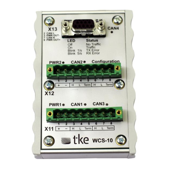
WCS-10
TKE WCS-10 Manuals
Manuals and User Guides for TKE WCS-10. We have
1
TKE WCS-10 manual available for free PDF download: User Manual
TKE WCS-10 User Manual (36 pages)
Brand:
TKE
| Category:
Control Unit
| Size: 0 MB
Table of Contents
Table of Contents
2
1 Legal Disclaimer
10
Exclusion of Liability
10
2 Hardware Specifications
11
Technical Details
11
Mechanical Dimensions
11
Figure 1: Mechanical Dimensions
11
Connectors
12
Figure 2: WCS-10 Connectors
12
Block Schema
13
Figure 3: WCS-10.04 Block Schema
13
Termination
14
Power Supply
14
Transceivers
14
Isolation
14
PE Grounding
14
Table 1: Power Supply Characteristics
14
Figure 4: Internal Termination
14
Light Emitting Diodes (LED)
15
3 Device Overview (WCS-10)
15
Introduction
15
Table 2: Power Led Status
15
Table 3: CAN Controller Led Status
15
Table 4: Priority of Led Indication States
15
Table 5: Blink Led Times
15
Wcs-10
16
CAN-Port Usage
16
Factory Settings
16
4 Device Configuration
17
Object Dictionary Overview
17
Table 6: Communication Profile Area
17
Table 7: Manufacturer-Specific Area
17
Table 25: 0X5010
17
Table 8: Device-Profile Specific Area
18
Global Parameters
19
Device Type (0X1000)
19
Node-ID (0X100B)
19
Table 9: 0X1000 Object Description
19
Table 10: 0X1000 Entry Description
19
Table 11: 0X100B Object Description
19
Table 12: 0X100B Entry Description
19
Store Parameters (0X1010)
20
Table 13: 0X1010 Object Description
20
Table 14: 0X1010 Entry Description
20
Table 15: Storage Write Access Signature
20
Inhibit Time of EMCY (0X1015)
21
Producer Heartbeat Time (0X1017)
21
Table 16: 0X1015 Object Description
21
Table 17: 0X1015 Entry Description
21
Table 18: 0X1017 Object Description
21
Table 19: 0X1017 Entry Description
21
Device Identity (0X1018)
22
Table 20: 0X1018 Object Description
22
Table 21: 0X1018 Entry Description
22
Table 22: Revision Number Structure
22
Hardware Configuration
23
Disable/Enable Heartbeat
23
Bit Rates (0X50X0)
23
Table 23: 0X2000 Object Description
23
Table 24: 0X2000 Entry Description
23
Table 26: 0X5010
23
Table 27: 0X5010..0X5050 Sub 0X02 BTR1 Entry Description
24
Table 28: Bit Rate Register Enumeration for 1000Kbps
24
Table 29: Bit Rate Register Enumeration for 800Kbps
24
Table 30: Bit Rate Register Enumeration for 500Kbps
24
Table 31: Bit Rate Register Enumeration for 250Kbps
24
Table 32: Bit Rate Register Enumeration for 125Kbps
24
Table 33: Bit Rate Register Enumeration for 100Kbps
24
Acceptance Filter Configurations First Filter Bank (0X50X1)
25
Table 34: Bit Rate Register Enumeration for 50Kbps
25
Table 35: 0X50X1 Object Description
25
Table 36: 0X50X1 Entry Description
25
Table 37: Acceptance Register Mapping
25
Acceptance Filter Configurations Second Filter Bank (0X50X2)
26
Table 38: 0X50X2 Object Description
26
Table 39: 0X50X2 Entry Description
26
Table 40: Acceptance Register Mapping
26
Acceptance Mask Configurations First Filter Bank (0X50X5)
27
Table 41: 0X50X5 Object Description
27
Table 42: 0X50X5 Entry Description
27
Table 43: Acceptance Mask Register Mapping
27
Acceptance Mask Configurations Second Filter Bank (0X50X6)
28
Table 44: 0X50X6 Object Description
28
Table 45: 0X50X6 Entry Description
28
Table 46: Acceptance Mask Register Mapping
28
Hardware Filter Configuration (0X50X9)
29
Table 47: 0X50X9 Object Description
29
Table 48: 0X50X9 Entry Description
29
Table 49: HW Filter Configuration Description
29
Filter Example for Two 32-Bit Filters Using Extended ID
30
Figure 5: 32-Bit Filter Using Extended ID Register
30
Figure 6: 32-Bit Filter Using Extended ID Register Only Accepting Extended CAN ID 0X1
30
Filter Example for Two 32-Bit Filters Using Standard ID
31
Table 50: 32-Bit Filter Extended ID Example
31
Figure 7: 32-Bit Filter Using Standard ID Register
31
Table 51: 32-Bit Filter Standard ID Example
32
Figure 8: 32-Bit Filter Using Standard ID Register Only Accepting Standard CAN ID 0X1
32
Universal ID Routing Setting
33
Route Table Configuration (0X6801
33
Table 52: Universal ID Routing Settings
33
Table 53: 0X6800 Sub 1 Entry Description CAN-ID
33
Table 54: 0X6800 Sub2 Entry Description Route
33
Table 55: Route Table Configuration
33
Table 56: 0X6801..0X6864 Entry Description CAN-ID
34
Table 57: 0X6801..0X6864 Sub2 Entry Description Route
34
Table 58: Route Descriptor Structure
34
5 Error Message
36
Table 59: Error Message Descriptions
36
Table 60: Error Message Structure
36
Advertisement
Advertisement
Related Products
TKE Categories
Stairlifts
Measuring Instruments
Control Unit
Elevators
Controller
More TKE Manuals
Login
Sign In
OR
Sign in with Facebook
Sign in with Google
Upload manual
Upload from disk
Upload from URL