
Summary of Contents for TKE WCS-10
- Page 1 WCS-10 User manual WCS-10 USER MANUAL WCS-10 manual version 1.41 Firmware version 0x1002b Marine Type Approvals info@tke.fi www.tke.fi Copyright © TK Engineering Oy 2009 - 2017...
-
Page 2: Table Of Contents
Transceivers ....................14 Isolation ......................14 PE Grounding ....................14 2.10 Light Emitting Diodes (LED) ..............15 3 Device Overview (WCS-10) ..............15 Introduction ....................15 WCS-10 ......................16 CAN-Port usage ..................... 16 Factory settings ....................16 4 Device Configuration ................17 Object dictionary overview ................ - Page 3 WCS-10 User manual Global parameters ..................19 4.2.1 Device type (0x1000) ................19 4.2.2 Node-ID (0x100B) .................. 19 4.2.3 Store parameters (0x1010) ..............20 4.2.4 Inhibit time of EMCY (0x1015) ............. 21 4.2.5 Producer heartbeat time (0x1017) ............21 4.2.6 Device identity (0x1018) ................
- Page 4 WCS-10 User manual List of tables Table 1: Power supply characteristics ................. 14 Table 2: Power led status ..................... 15 Table 3: CAN controller led status ................15 Table 4: Priority of led indication states ..............15 Table 5: Blink led times ....................15 Table 6: Communication profile area ................
- Page 5 WCS-10 User manual Table 42: 0x50x5 entry description ................27 Table 43: Acceptance mask register mapping............. 27 Table 44: 0x50x6 object description ................28 Table 45: 0x50x6 entry description ................28 Table 46: Acceptance mask register mapping............. 28 Table 47: 0x50x9 object description ................29 Table 48: 0x50x9 entry description ................
- Page 6 List of figures Figure 1: Mechanical dimensions ................11 Figure 2: WCS-10 connectors ..................12 Figure 3: WCS-10.04 Block schema ................13 Figure 4: Internal termination..................14 Figure 5: 32-bit filter using extended ID register ............30 Figure 6: 32-bit filter using extended ID register only accepting extended CAN ID 0x1 ..........................
- Page 7 BCAB Changed help text in EMCY-codes table 30.12.08 1.21 BCAB Changed EMCY bus state messages and firmware version 05.01.09 1.22 BCAB Changed EMCY, firmware updated, WCD-10 changed to WCS-10, Changed front page picture. 07.01.09 1.23 BCAB WCS-10 front page picture changed 19.01.09 1.24...
- Page 8 WCS-10 User manual 12.06.09 1.39 BCAB GL type approval status changed 19.01.17 1.41 Front page picture changed to one with TKE logo, spelling fixes © TK Engineering Oy, 2009. All rights reserved. Copyright © TK Engineering Oy 2009 - 2017...
- Page 9 WCS-10 User manual References /2/ MC9S12XDP512 Data Sheet, Rev. 2.11, Freescale Semiconductor /3/ CiA301, CiA Draft Standard Proposal 301, V4.1 /4/ Embedded Networking with CAN and CANopen, Pfeiffer, Ayre and Keydel /5/ CiA302-1, CiA Addition application layer functions, V3.4.1 /6/ CiA Draft Recommendation 303-3 Indicator specification V1.2...
-
Page 10: Legal Disclaimer
Do not use WCS-10 if you are not absolutely certain that you know how to use the WCS-10. If you are uncertain about compatibility between WCS-10 and your system, do not use WCS-10 in your system. -
Page 11: Hardware Specifications
WCS-10 User manual 2 Hardware specifications 2.1 Technical details Operating voltage 10…40V DC. Power consumption max 3.5W typical 3W CAN routing ports, CAN1 – CAN4, galvanically isolated 1kV, ISO11898, Max 1Mbps CAN configuration port, CANA, ISO11898, Max 1Mbps ... -
Page 12: Connectors
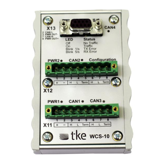
WCS-10 User manual 2.3 Connectors The WCS-10 has 2 Phoenix MSTBV 2,5/8-GF-5,08-AU connectors and one DSUB 9 pin Female connector Tyco AMP 3-388313-2 Phoenix MSTBV 2,5/8-GF-5,08-AU Phoenix MSTBV 2,5/8-GF-5,08-AU X11.1 PWR 1+ X12.1 PWR 2+ X11.2 PWR 1- X12.2 PWR 2- X11.3... -
Page 13: Block Schema
WCS-10 User manual 2.4 Block schema Figure 3: WCS-10.04 Block schema Copyright © TK Engineering Oy 2009 - 2017... -
Page 14: Termination
CAN L the CAN bus can be terminated. CAN 4 is always terminated at the WCS-10. 2.6 Power supply The WCS-10 must be powered by DC voltage from 10 to 40 Volt. The WCS-10 has dual power inputs and can be powered on both simultaneous or on only one of the two. The max power consumption when stress tested was 3,5W. -
Page 15: Light Emitting Diodes (Led)
WCS-10 User manual 2.10 Light Emitting Diodes (LED) The WCS-10 have 6 led’s, two green and four yellow. The green ones are for input voltage monitoring. When input voltage drops below 10VDC the power led’s switches off. The yellow CAN led’s indicates different CAN controller states. -
Page 16: Wcs-10
WCS-10 User manual 3.2 WCS-10 WCS-10 is a product name for a product originally targeted to connect up to 4 CAN buses running different protocols with each other. The WCS-10 takes care of forwarding CAN-messages, CAN- ID, DLC and data contents according to the configuration. The WCS-10 support bit rate configurations on each CAN-port. -
Page 17: Device Configuration
WCS-10 User manual 4 Device Configuration While the WCS-10 is CAN networking device, configuration is object-dictionary oriented to enable use of standard CANopen configuration tools, EDS- and DCF-files. 4.1 Object dictionary overview Table 6: Communication profile area Index Sub-idx Type... -
Page 18: Table 8: Device-Profile Specific Area
WCS-10 User manual 0x5030 CAN3 bit rate 0x00 Largest sub-index supported 0x01 CAN3 register BTR0 0x02 CAN3 register BTR1 0x5031 0x00 CAN3 acceptance filter, bank 0 0x5031 0x00 CAN3 acceptance filter, bank 1 0x5035 0x00 CAN3 acceptance mask, bank 0... -
Page 19: Global Parameters
WCS-10 User manual 4.2 Global parameters 4.2.1 Device type (0x1000) Device type indicates rough category of the device. WCS-10 equals pure CANopen-device without any device-profile specific functionality or application programmability. No additional information is provided. Table 9: 0x1000 object description... -
Page 20: Store Parameters (0X1010)
WCS-10 User manual 4.2.3 Store parameters (0x1010) When storing parameters, the device stores the configuration and routing-table in non-volatile memory (flash). The device does not support automated storing. When storing data, the device follows the standard Ref /3/. The value to send is ASCII value for “SAVE”. -
Page 21: Inhibit Time Of Emcy (0X1015)
WCS-10 User manual 4.2.4 Inhibit time of EMCY (0x1015) Table 16: 0x1015 object description Attribute Value Index 0x1015 Name Inhibit time EMCY Object code Variable Data type Category Optional Table 17: 0x1015 entry description Attribute Value Sub-index 0x00 Access PDO mapping Value range U16 (multiple of 100s) -
Page 22: Device Identity (0X1018)
WCS-10 User manual 4.2.6 Device identity (0x1018) Table 20: 0x1018 object description Attribute Value Index 0x1018 Name Identity object Object code Record Data type Identity Category Mandatory Table 21: 0x1018 entry description Attribute Value Sub-index 0x00 Description Highest sub-index supported... -
Page 23: Hardware Configuration
4.3 Hardware configuration 4.3.1 Disable/Enable Heartbeat The WCS-10 has a configuration port that is using the CANopen stack specifications. This port uses to configure the node, and it also transmits heartbeat and EMCY messages. This port can disable and enable the heartbeat by writing to SDO object 0x2000. Writing 0 disables the heartbeat, writing 1 enables, which is default. -
Page 24: Table 27: 0X5010..0X5050 Sub 0X02 Btr1 Entry Description
WCS-10 User manual Table 27: 0x5010..0x5050 sub 0x02 BTR1 entry description Attribute Value Sub-index 0x3A Access PDO mapping Value range See Table 28 to Table 34 Default value 0x1C (500 kbps) These tables below about bit rates are examples and pre-calculated bit rates for the MSCAN controller and with oscillator clock 16 MHz. -
Page 25: Acceptance Filter Configurations First Filter Bank (0X50X1)
WCS-10 User manual Table 34: Bit rate register enumeration for 50kbps Nr Time quanta Sample Point % Register BTR0 Register BRT1 87,5 0x13 0x1C 75 0x13 0x3A 62,5 0x13 0x58 The new settings will apply after made a “Save configuration” request and when made a software/hardware reboot. -
Page 26: Acceptance Filter Configurations Second Filter Bank (0X50X2)
WCS-10 User manual 4.3.4 Acceptance filter configurations second filter bank (0x50x2) Table 38: 0x50x2 object description Attribute Value Index 0x5012 (CAN1), 0x5022 (CAN2), 0x5032 (CAN3), 0x5042 (CAN4) Name Port [1..4] acceptance filter configuration Object code Variable Data type Category Optional... -
Page 27: Acceptance Mask Configurations First Filter Bank (0X50X5)
WCS-10 User manual 4.3.5 Acceptance mask configurations first filter bank (0x50x5) Table 41: 0x50x5 object description Attribute Value Index 0x5015 (CAN1), 0x5025 (CAN2), 0x5035 (CAN3), 0x5045 (CAN4) Name Port [1..4] acceptance mask configuration Object code Variable Data type Category Optional... -
Page 28: Acceptance Mask Configurations Second Filter Bank (0X50X6)
WCS-10 User manual 4.3.6 Acceptance mask configurations second filter bank (0x50x6) Table 44: 0x50x6 object description Attribute Value Index 0x5016 (CAN1), 0x5026 (CAN2), 0x5036 (CAN3), 0x5046 (CAN4) Name Port [1..4] acceptance mask configuration Object code Variable Data type Category Optional... -
Page 29: Hardware Filter Configuration (0X50X9)
WCS-10 User manual 4.3.7 Hardware filter configuration (0x50x9) There are 4 different filter configurations which the WCS-10 supports. More detailed information is found in reference /2/ Chapter 13.3.2.12. Filter configuration changes register CANIDAC fields IDAM0-IDAM1. Table 47: 0x50x9 object description... -
Page 30: Filter Example For Two 32-Bit Filters Using Extended Id
WCS-10 User manual 4.3.8 Filter example for two 32-bit filters using extended ID The picture below shows the function of one of the two per channel 32-bit filters when using extended CAN IDs. For a filter to produce a “hit” the ID in CAN controller register is masked with the value in the CAN controller acceptance mask register against the value in the CAN controller acceptance register. -
Page 31: Filter Example For Two 32-Bit Filters Using Standard Id
WCS-10 User manual To set WCS-10 CAN 1 to use two 32-bit filters with filter one only accepting an extended ID with CAN ID 0x1 and filter two accepting only extended CAN ID 0x2 Table 50: 32-bit filter extended ID example... -
Page 32: Table 51: 32-Bit Filter Standard Id Example
Figure 8: 32-bit filter using standard ID register only accepting standard CAN ID 0x1 To set WCS-10 CAN 1 to use two 32-bit filters with filter one only accepting an standard ID with CAN ID 0x1 and filter two accepting only standard CAN ID 0x2... -
Page 33: Universal Id Routing Setting
WCS-10 User manual 4.4 Universal ID routing setting This is used if you want all can-id to have the same routing settings. If value of routing settings is something else than 0x0000 then this routing settings will be used and the routing table 0x6801 to 0x6864 will be ignored. -
Page 34: Table 56: 0X6801..0X6864 Entry Description Can-Id
WCS-10 User manual Table 56: 0x6801..0x6864 entry description CAN-ID Attribute Value Sub-index 0x01 Description CAN id Access PDO mapping Value range Default value 0x00000000 NOTE: Standard id 0x3f and extended id 0x3f are handled separately, to define an extended id, bit 30 in ID field must be set to 1. - Page 35 WCS-10 User manual Example 1: 0x6801:0x01 = 0x3f: (array index 0) 0x6801:0x02 = 0x0356: (array index 0) 0: Messages with ID 0x3f received from CAN4 are discarded 3: Messages with ID 0x3f received from CAN3 are copied to CAN1 and CAN2...
-
Page 36: Error Message
WCS-10 User manual 5 Error message The error messages (EMCY) are using CANopen protocol as template. Software is producing tree types of error messages for each CAN interface. The error messages are defined in table below. Table 59: Error message descriptions...
Need help?
Do you have a question about the WCS-10 and is the answer not in the manual?
Questions and answers