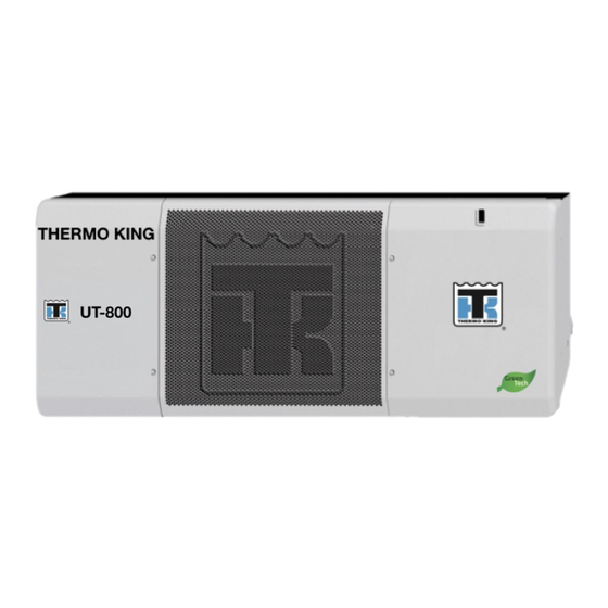
Sign In
Upload
Manuals
Brands
Thermo King Manuals
Automobile Accessories
UT-800
Thermo King UT-800 Manuals
Manuals and User Guides for Thermo King UT-800. We have
4
Thermo King UT-800 manuals available for free PDF download: Operator's Manual, Maintenance Manual, Manual
Thermo King UT-800 Operator's Manual (662 pages)
Brand:
Thermo King
| Category:
Automobile Accessories
| Size: 6.04 MB
Table of Contents
English
4
Table of Contents
4
Introduction
6
General Information
6
Thermo Assistance
6
First Aid and Safety
7
Refrigerant
7
Refrigerant Oil
7
Refrigerant Information
7
Safety Precautions
7
Electrical Hazard
8
Electric Standby
8
Cycle-Sentry
8
Unit Description
9
General Description
9
Design Features
9
Unit Options
9
Engine
10
ELC (Extended Life Coolant)
10
Clutch
10
Scroll Compressor
10
HMI Control Panel
10
DAS - Data Acquisition System (Optional)
11
Defrost
11
CYCLE-SENTRYTM System
11
Electric Standby
12
Engine Compartment Components
12
Unit Protection Devices
13
Specifications
15
Engine TK 376U
15
Belt Tension
16
R-404A/R-452A
17
Electrical Control System
18
Standby Power Requirements
18
Fuses
19
Electrical Standby (Model 50 Units Only) UT-1200, UT-1200 Spectrum, UT-800
20
Unit Operating Instructions Standard TSR-3 HMI Controller
21
The Multi-Temperature Display and Zone Indicators
24
Starting the Diesel Engine
25
Starting the Electric Motor
25
Alarms
26
Pretrip Test
26
Display Brightness
27
Checking Truck HMI Control Panel Software Revision and Serial Number
28
Keypad Lockout
28
Unit Operating Instructions Premium HMI Controller
29
Keys
30
Turning the Unit on and off
31
The Standard Display
32
Operating the Unit in Single Zone Control Mode (SPECTRUM)
33
Starting the Diesel Engine
34
Starting the Electric Motor
34
Main Menu Overview (SPECTRUM)
34
Using the Main Menu
35
Alarms
36
Hourmeters
40
Datalogger
40
Mode
41
Selecting CYCLE-SENTRY or Continuous Mode
43
Selecting Sleep Mode
44
Pretrip
46
Diesel/Electric Menu
48
Adjust Brightness
50
Time
50
TSR/TSR-3 Alarm Codes
51
Electric Standby Operation
57
Electric Power Receptacle
57
Pre-Trip Inspection
58
Care and Maintenance
58
After Start Inspection
59
Loading
59
Warranty
62
Serial Number and Refrigerant Label Locations
64
Français
66
Informations Générales
68
Introduction
68
Thermo Assistance
68
Fluide Frigorigène
69
Huile de Réfrigération
69
Informations Relatives au Réfrigérant
69
Mesures de Sécurité
69
Premiers Secours et Sécurité
69
Cycle-Sentry
70
Mode Électrique
70
Risques D'électrocution
70
Caractéristiques de Conception
71
Description de le Groupe
71
Description Générale
71
Options du Groupe
71
Compresseur Scroll
72
ELC (Liquide de Refroidissement Longue Durée)
72
Embrayage
72
Moteur
72
Panneau de Commande HMI
72
Cycle-Sentrysystème
73
Dégivrage
73
Système de Collecte des Données ou das (en Option)
73
Composants du Compartiment Moteur
74
Mode D'alimentation Électrique
74
Dispositifs de Protection du Groupe
75
Caractéristiques Techniques
77
Moteur TK 376U
77
Tension de la Courroie
78
R-404A/R-452A
79
Exigences pour L'alimentation en Mode Secteur
80
Système de Commande Électrique
80
Fusibles
81
Mode Électrique (Groupes Modèle 50 Uniquement)
82
Spectrum, UT-800
82
Contrôleur TSR-3 Avec HMI Standard - Instructions de Fonctionnement du Groupe
83
Affichage Multi-Températures et Témoins de Zone
86
Démarrage du Moteur Thermique
87
Démarrage du Moteur Électrique
87
Alarmes
88
Test Avant-Trajet
89
Luminosité de L'affichage
90
Verrouillage du Clavier
90
Vérification de la Version Logicielle et du Numéro de Série du Panneau de Commande HMI
90
Panneau de Commande HMI Haut de Gamme - Instructions de Fonctionnement du Groupe
91
Touches
92
Mise en Marche et Mise à L'arrêt du Groupe
93
Écran D'affichage Standard
94
Fonctionnement du Groupe en Mode Contrôle de Zone Unique (SPECTRUM)
95
Démarrage du Moteur Thermique
96
Démarrage du Moteur Électrique
96
Présentation du Menu Principal (SPECTRUM)
96
Utilisation du Menu Principal
97
Alarmes
98
Collecteur de Données
102
Compteurs Horaires
103
Mode
104
Sélection du Mode de Fonctionnement CYCLE-SENTRY ou Continu
105
Sélection du Mode Veille
106
Avant-Trajet
108
Menu du Mode Thermique/Électrique
110
Date et Heure
112
Réglage de la Luminosité
112
Codes D'alarme pour TSR/TSR-3
113
Fonctionnement en Mode Électrique
119
Prise de Courant Électrique
119
Inspection Avant-Trajet
120
Soin et Entretien
120
Chargement
121
Inspection après le Démarrage
121
Garantie
124
Emplacements des Étiquettes Indiquant le Type de Réfrigérant et le Numéro de Série
126
Italiano
128
Informazioni Generali
130
Introduzione
130
Thermo Assistance
130
Informazioni Relative al Refrigerante
131
Olio Refrigerante
131
Pronto Soccorso Emisure DI Sicurezza
131
Refrigerante
131
Cycle-Sentry
132
Misure DI Sicurezza
132
Modalità Elettrica DI Riserva
132
Pericolo DI Scariche Elettriche
132
Caratteristiche DI Design
133
Descrizione Delle Unità
133
Descrizione Generale
133
Opzioni Dell'unità
133
Compressore a Spirale
134
Elc (Liquido DI Raffreddamentoa Durata Prolungata)
134
Frizione
134
Motore Diesel
134
Quadro Comandi HMI
134
Alimentazione Elettrica DI Riserva
135
DAS (Data Acquisition System, Sistema DI Acquisizione Dati) Opzionale
135
Sbrinamento
135
Sistema CYCLE-SENTRY
135
Componenti del Vano Motore
136
Dispositivi DI Protezione Dell'unità
137
Caratteristiche Tecniche
139
Motore Diesel TK 376U
139
Tensione Della Cinghia
140
R-404A/R-452A
141
Requisiti Per L'alimentazione Elettrica DI Riserva
142
Sistema DI Controllo Elettrico
142
Fusibili
143
Funzionamento Elettrico DI Riserva
144
Spectrum, UT-800
144
Sistema DI Controllo HMI Standard TSR-3 - Istruzioni Operative Dell'unità
145
Display E Indicatori Della Zona Nel Sistema Multitemperatura
149
Allarmi
150
Avviamento del Motore Diesel
150
Avviamento del Motore Elettrico
150
Verifica Prima Della Partenza
151
Blocco Tastiera
153
Controllo del Numero DI Versione E del Numero DI Serie del Software del Quadro Comandi HMI Degli Autocarri
153
Luminosità del Display
153
Sistema DI Controllo HMI Premium - Istruzioni Operative Dell'unità
155
Tasti
156
Accensione E Spegnimento Dell'unità
157
Display Standard
158
Funzionamento Dell'unità in Modalità Controllo a Zona Singola (Spectrum)
159
Avviamento del Motore Diesel
160
Avviamento del Motore Elettrico
160
Schema del Menu Principale (Spectrum)
160
Utilizzo del Menu Principale
161
Allarmi
162
Registratore Dati
166
Contaore
167
Modalità
168
Selezione Della Modalità CYCLE-SENTRY O Continua
169
Selezione Della Modalità Riposo
170
Verifica Prima Della Partenza
172
Menu Diesel/Elettrico
174
Orario
176
Regolazione Della Luminosità
176
Codici DI Allarme TSR/TSR-3
177
Funzionamento in Modalità Elettrica DI Riserva
185
Presa DI Alimentazione Elettrica
185
Cura E Manutenzione
186
Ispezione Pre-Viaggio
186
Ispezione Postavviamento
187
Procedura DI Carico
187
Garanzia
190
Posizione del Numero DI Serie E Delle Etichette del Refrigerante
192
Deutsch
194
Allgemeines
196
Einleitung
196
Thermo Assistance
196
Erste Hilfe und Sicherheit
197
Kältemittel
197
Kältemittelinformationen
197
Kältemittelöl
197
Cycle-Sentry
198
Gefahren durch Elektrizität
198
Netzbetrieb
198
Sicherheitshinweise
198
Allgemeine Beschreibung
199
Designmerkmale
199
Gerätebeschreibung
199
Geräteoptionen
199
Dieselmotor
200
ELC (Langzeitkühlmittel)
200
HMI-Reglerschalttafel
200
Kupplung
200
Spiralkompressor
200
Abtaubetrieb
201
CYCLE-SENTRY™-System
201
DAS - Datenerfassungssystem (Optional)
201
Netzbetrieb
201
Motorrauminstrumente
202
Schutzvorrichtungen des Geräts
202
Motor TK 376U
205
Technische Daten
205
Riemenspannung
206
R-404A/R-452A
207
Elektrisches Reglersystem
208
Voraussetzungen für den Netzbetrieb
208
Sicherungen
209
Netzbetrieb (nur Modell-50-Geräte) UT-1200, UT-1200 Spectrum, UT-800
210
Betriebsanweisungen für Standard-TSR-3-HMI- Regler
211
Mehrfachtemperaturanzeige und Anzeigeleuchten für Zonen
215
Alarme
216
Starten des Dieselmotors
216
Starten des Elektromotors
216
Kontrolle vor Fahrtbeginn
217
Der HMI-Reglerschalttafel für LKW
219
Helligkeit der Anzeige
219
Tastensperre
219
Überprüfen von Softwareversion und Seriennummer
219
Betriebsanweisungen für Premium HMI-Regler
221
Tasten
222
Ein- und Ausschalten des Geräts
223
Die Standardanzeige
224
Gerätebetrieb mit Einzonenregelung (SPECTRUM)
225
Starten des Dieselmotors
226
Starten des Elektromotors
226
Hauptmenüfunktionen (SPECTRUM)
227
Verwendung des Hauptmenüs
227
Alarme
228
Datenlogger
232
Stundenzähler
233
Betriebsart
234
Auswahl von CYCLE-SENTRY- oder Dauerbetrieb
236
Auswahl des Ruhebetriebs
237
Kontrolle vor Fahrtbeginn
239
Menü für Diesel-/Netzbetrieb
242
Helligkeit Einstellen
243
Zeit
244
TSR/TSR-3-Alarmcodes
245
Netzbetrieb
253
Stromanschlussbuchse
253
Inspektion vor Fahrtbeginn
254
Pflege und Wartung
254
Inspektion nach dem Start
255
Ladeverfahren
255
Garantie
258
Anbringung des Seriennummern- und Kältemittelschildes
260
Español
262
Información General
264
Introducción
264
Thermo Assistance
264
Aceite Refrigerante
265
Información sobre el Refrigerante
265
Primeros Auxiliosy Seguridad
265
Refrigerante
265
Cycle-Sentry
266
Funcionamiento Eléctrico
266
Peligro Eléctrico
266
Precauciones de Seguridad
266
Características de Diseño
267
Descripción de la Unidad
267
Descripción General
267
Opciones de la Unidad
267
Compresor de Espiral
268
ELC (Líquido Refrigerante de Mayor Duración)
268
Embrague
268
Motor
268
Panel de Control de la HMI
268
DAS (Sistema de Adquisición de Datos), Opcional
269
Descarche
269
Sistema CYCLE-SENTRY
269
Componentes del Compartimento del Motor
270
Funcionamiento Eléctrico
270
Dispositivos de Protección de la Unidad
271
Características Técnicas
273
Motor TK376U
273
Tensión de la Correa
274
R-404A/R-452A
275
Requisitos del Sistema Eléctrico
276
Sistema de Control Eléctrico
276
Fusibles
277
Funcionamiento Eléctrico (solo en las Unidades del Modelo 50): UT-1200, UT-1200 Spectrum y UT-800
278
Instrucciones de Funcionamiento de la Unidad: Controlador de la HMI Estándar del TSR-3
279
La Pantalla Multitemperaturay Los Indicadores de Zona
283
Alarmas
284
Puesta en Marcha del Motor DIésel
284
Puesta en Marcha del Motor Eléctrico
284
Prueba de Revisión Antes del Viaje
285
Bloqueo del Teclado
287
Brillo de la Pantalla
287
Comprobación del Número de Serie y la Versión del Software del Panel de Control de la HMI para Camión
287
Instrucciones de Funcionamiento de la Unidad: Controlador de la HMI de Calidad Superior
289
Teclas
290
Encendido y Apagado de la Unidad
291
La Pantalla Estándar
292
Funcionamiento de la Unidad en Modo de Control de Zona Única (Spectrum)
293
Puesta en Marcha del Motor DIésel
294
Puesta en Marcha del Motor Eléctrico
294
Presentación General del Menú Principal (Spectrum)
295
Utilización del Menú Principal
295
Alarmas
296
Registrador de Datos
300
Contadores Horarios
301
Modo
302
Selección del Modo de Funcionamiento Cycle-Sentry Odel Modo de Funcionamiento Continuo
304
Selección del Modo Inactivo
305
Revisión Antes del Viaje
307
Menú DIésel/Eléctrico
310
Ajuste del Brillo
311
Tiempo
312
Códigos de Alarma del TSR/TSR-3
313
Funcionamiento Eléctrico
319
Receptáculo de Alimentación Eléctrica
319
Cuidados y Mantenimiento
320
Inspección Antes del Viaje
320
Inspección Después del Arranque
321
Procedimiento de Carga
321
Garantía
324
Ubicación de Los Números de Seriey de la Etiqueta del Refrigerante
326
Русский
328
Введение
330
Общие Сведения
330
Служба Thermo Assistance
330
Информация О Хладагентах
331
Меры Предосторожности
331
Первая Помощь Итехника Безопасности
331
Рефрижераторное Масло
331
Хладагент
331
Режим CYCLE-SENTRY
332
Резервный Электропривод
332
Электробезопасность
332
Дополнительные Элементы Установки
333
Общее Описание
333
Описание Установки
333
Особенности Конструкции
333
ELC (Охлаждающая Жидкость С Увеличенным Сроком Службы)
334
Двигатель
334
Муфта
334
Панель Управления HMI
334
Спиральный Компрессор
334
DAS - Система Сбора Данных (Дополнительно)
335
Оттайка
335
Система CYCLE-SENTRY
335
Компоненты Отсека Двигателя
336
Резервный Электропривод
336
Устройства Защиты Установки
337
Двигатель TK 376U
339
Технические Характеристики
339
Натяжение Ремня
340
R-404A/R-452A
341
Потребляемая Мощность Резервного Электропривода
342
Система Управления Электрооборудованием
342
Предохранители
343
Модели 50): UT-1200, UT-1200 Spectrum, UT-800
344
Резервный Электропривод
344
Инструкции По Эксплуатации Установки Со Стандартным Контроллером TSR-3 HMI
345
Мультитемпературный Дисплей И Индикаторы Зоны
349
Запуск Дизельного Двигателя
350
Запуск Электродвигателя
350
Аварийная Сигнализация
351
Предрейсовая Проверка
352
Блокировка Кнопочной Панели
353
Проверка Версии Программного Обеспечения И Серийного Номера Панели Управления HMI Для Грузовых Автомобилей
353
Яркость Дисплея
353
Инструкции По Эксплуатации Установки С Контроллером HMI Premium
355
Кнопки
356
Включение И Выключение Установки
357
Стандартный Экран Дисплея
358
Эксплуатация Установки Врежиме Управления Одной Зоной (Spectrum)
359
Запуск Дизельного Двигателя
360
Запуск Электродвигателя
360
Обзор Главного Меню (SPECTRUM)
360
Использование Главного Меню
361
Аварийная Сигнализация
362
Регистратор Данных
366
Счётчики Наработки
367
Режим
368
Выбор Режима CYCLE-SENTRY Или Непрерывного Режима
369
Выбор Спящего Режима
370
Предрейсовая Проверка (Pretrip)
373
Меню Работы От Дизельного/Электрического Привода
376
Время
377
Регулировка Яркости
377
Коды Аварийной Сигнализации TSR/TSR-3
379
Гнездо Подключения Источника Питания
389
Режим Резервного Электропривода
389
Предрейсовый Осмотр
390
Уход И Техническое Обслуживание
390
Погрузка
391
Послепусковая Проверка
391
Гарантия
394
Расположение Табличек С Серийным Номером И Указанием Типа Хладагента
396
Advertisement
Thermo King UT-800 Manual (169 pages)
Brand:
Thermo King
| Category:
Refrigerator
| Size: 9.25 MB
Table of Contents
Table of Contents
5
List of Figures
11
Safety Precautions
15
General Practices
15
Auto Start/Stop
16
Battery Installation and Cable Routing
16
Battery Removal
16
Refrigerant Hazards
16
Refrigerant Oil Hazards
17
Electrical Hazards
17
High Voltage
17
Low Voltage
18
Microprocessor Service Precautions
18
Welding Precautions
18
First Aid
19
First Aid, Refrigerant
19
First Aid, Refrigerant Oil
19
First Aid, Engine Coolant
19
First Aid, Electrical Shock
19
Specifications
21
Engine
21
Engine Clutch
22
Belt Tension
22
Refrigeration System
22
Electrical Control System
22
Fuses
23
Electrical Components
23
Evaporator Fan Motors
24
Electrical Standby
24
Standby Power Requirements
24
Maintenance Inspection Schedule
25
Unit Description
27
General Description
27
Unit Features
27
Unit Options
27
Standard HMI Control Panel
27
Figure 1: Standard HMI Control Panel
27
Mechanics HMI Control Panel
28
Premium HMI Control Panel (Optional)
28
CYCLE-SENTRYTM Start/Stop System
28
DAS - Data Acquisition System (Optional)
28
Unit Protection Devices
28
Figure 2: Mechanics/Premium HMI Control Panel
28
Unit Component Identification
29
Figure 3: Front View (UT-1200 Shown, UT-800 Similar)
29
Figure 4: UT-800/UT-1200 Components, Front and Side Views (Panels Removed)
30
Figure 5: UT-800/UT-1200 Components, Rear View (Panels Removed)
30
Refrigeration System Components
31
Solenoids and Valves
31
Sensors, Switches, and Transducers
31
Refrigeration System Diagrams
33
Figure 6: Refrigeration System Components
33
Cool Mode
34
Figure 7: Cool Mode
34
Purge Mode
35
Figure 8: Purge Mode
35
Heat/Defrost Mode
36
Figure 9: Heat/Defrost Mode
36
Operating Instructions for Standard HMI Control Panel
37
Truck HMI Controller Description
37
SR-3 Truck HMI Controller
37
Display
37
Figure 10: SR-3 Truck HMI Controller
37
Figure 11: Display
37
Keys and LED Indicators
39
Figure 12: Keys and LED Indicators
39
Turning the Unit on and off
41
The Standard Display
41
Figure 13: Keys and LED Indicators
41
Figure 14: Electric Motor Run Time Hours and Electric Icon
41
Figure 15: Standard Display of Box Temperature and Setpoint
41
Figure 16: on Key
41
Figure 17: Standard Display
41
Changing the Setpoint
42
Starting the Diesel Engine
42
Figure 18: up ARROW Key
42
Figure 19: ENTER Key
42
Figure 20: Alarm Icon and Setpoint
42
Starting the Electric Motor
43
Switching from Diesel to Electric
43
Switching from Electric to Diesel
43
Figure 21: Standard Display
43
Figure 22: Standard Display
43
Selecting CYCLE-SENTRY or Continuous Mode
44
Figure 23: Alarm Icon
44
Figure 24: Press on Key
44
Figure 25: Display, Preferred Method for Manually Switching from Electric Mode to Diesel Mode
44
Selecting the High Speed Lock-Out Feature
45
Initiating a Manual Defrost Cycle
45
Figure 26: CYCLE-Sentry/Continuous Key
45
Figure 27: HIGH SPEED LOCKOUT Key
45
Figure 28: DEFROST Key
45
Alarms
46
Figure 29: Box Temperature will Rise Toward 50 F (10 C)
46
Figure 30: Alarm Icon
46
Figure 31: on and PRETRIP TEST Keys
46
Figure 32: ENTER Key
46
Figure 33: Standard Display
46
Sending a Servicewatch Data Logger Start of Trip
47
Pretrip Test
47
Pretrip Test Conditions
47
Conditions Where Pretrip Tests Are Not Allowed
47
Pretrip Test Sequence
47
Figure 34: ENTER Key
47
Pretrip Test Considerations
48
Performing a Pretrip Test
48
Starting a Pretrip Test
48
Figure 35: Pretrip Test
48
Figure 36: PRETRIP Key
48
Pretrip Test Results
49
Display Brightness
49
Figure 37: on Key, UP/DOWN Arrow Keys
49
Checking Truck HMI Control Panel Software Revision and Serial Number
50
Figure 38: PRETRIP Key
50
Figure 39: Software Revision and Serial Number
50
Operating Instructions for Premium HMI Control Panel
51
Truck Premium HMI Controller Description
51
Premium HMI Control Panel
51
Display
51
Figure 40: Premium HMI Control Panel
51
Keys
52
Hard Keys
52
Soft Keys
52
Turning the Unit on and off
52
Figure 41: Display
52
Figure 42: Keys
52
Figure 43: Soft Keys
52
If more than One Language Is Enabled
53
Figure 44: Thermo King Logo
53
Figure 45: Startup Screen
53
Figure 46: no Key
53
Figure 47: YES Key
53
Figure 48: Programming Language
53
Figure 49: Standard Display
53
Figure 50: First and Last Soft Keys
53
The Standard Display
54
Changing the Setpoint
54
Figure 51: Language Menu
54
Figure 52: Standard Display
54
Figure 53: Power down Message
54
Figure 54: off Display
54
Figure 55: Standard Display
54
Figure 56: SETPOINT Key
54
Figure 57: Setpoint Display
54
Starting the Diesel Engine
55
Figure 58: Increase Setpoint
55
Figure 59: Soft Keys
55
Figure 60: New Setpoint
55
Figure 61: Standard Display, New Setpoint
55
Starting the Electric Motor
56
Switching from Diesel to Electric
56
Figure 62: Engine Start Screen
56
Figure 63: Standard Display of Temperature and Setpoint
56
Figure 64: Motor Start Screen
56
Figure 65: Standard Display of Temperature and Setpoint
56
Figure 66: Prompt Screen, Guarded Access Set to no
56
Figure 67: Prompt Screen, Guarded Access Set to Yes
56
Switching from Electric to Diesel
57
Initiating a Manual Defrost Cycle
57
Figure 68: Prompt Screen, Standby Power Is Turned off or Is no Longer Available
57
Figure 69: Prompt Screen, after off and on
57
Figure 70: Display Is YES Is Selected
57
Figure 71: Press Defrost Key
57
Figure 72: Prompt Screen, Guarded Access Set to Yes
57
Terminating a Defrost Cycle
58
Selecting High Speed Lockout Mode (if Enabled)
58
Figure 73: Defrost Display
58
Figure 74: High Speed Lockout Key
58
Figure 75: PROGRAMMING HIGH SPEED LOCKOUT - PLEASE WAIT
58
Figure 76: High Speed Lockout Display
58
Figure 77: Standard Display, High Speed Lockout Active
58
Selecting CYCLE-SENTRY or Continuous Mode
59
Using the Gauges Key
59
Figure 78: Gauges Key
59
Figure 79: Next, Back, Lock Keys
59
Using the Sensors Key
60
Using the Main Menu
60
Figure 80: Sensors Key
60
Figure 81: Next, Back, Lock Keys
60
Figure 82: Menu Key
60
Figure 83: Pretrip Submenu
60
Main Menu Choices
61
Languages
61
Figure 84: Menu Key
62
Figure 85: Select Key
62
Figure 86: + or - Keys, Yes Key
62
Figure 87: New Language
62
Figure 88: Standard Display in New Language
62
Figure 89: Standard Display in New Language
62
Figure 90: Language Menu
62
Alarms
63
Figure 91: Log Alarm Notice
63
Figure 92: Alarm Icon
64
Figure 93: Menu Key
65
Figure 94: Select Key
65
Figure 95: no Alarms
65
Figure 96: Alarm Code 6
65
Figure 97: Next Key
65
Figure 98: Help Key
65
Datalogger
66
Hourmeters
66
Figure 99: Menu Key
66
Figure 100: Select Key
66
Figure 101: Start of Trip
66
Figure 102: Select Key
66
Mode
67
Figure 103: Menu Key
67
Figure 104: Hourmeter Display
67
Figure 105: Scroll through Hourmeters
67
Selecting CYCLE-SENTRY or Continuous Mode
68
Figure 106: Menu Key
68
Figure 107: Select Key
68
Figure 108: Select and Next Keys
68
Figure 109: Menu Key
68
Figure 110: Select Key
68
Selecting Sleep Mode
69
Figure 111: Turn Off/Turn on CYCLE-SENTRY Screen
69
Figure 112: Select Key
69
Figure 113: Mode Change Confirmed
69
Figure 114: Mode Confirmed
69
Figure 115: Mode Menu
69
Figure 116: Menu Key
69
Figure 117: Select Key
70
Figure 118: Sleep Mode Menu
70
Figure 119: Start of Sleep Mode Menu
70
Figure 120: Select no to Enter Sleep Mode
70
Figure 121: Sleep Mode Display
70
Figure 122: Yes Key
70
Figure 123: Day Unit Is to Restart
70
Figure 124: Confirm Hour
70
Pretrip
71
Figure 125: Confirm Minute
71
Figure 126: Press Yes Key for Pretrip Test
71
Figure 127: Sleep Mode
71
Figure 128: Menu Key
72
Figure 129: Select Key
72
Figure 130: Running Pretrip
72
Figure 131: no Pretrip Prompt
72
Diesel/Electric Menu
73
Figure 132: Pretrip Test Display
73
Figure 133: Performing Cool Test
73
Figure 134: Pass, Check or Fail
73
Figure 135: Standby Power Connected & Available
73
Figure 136: Display When YES Is Selected
73
Adjust Brightness
74
Figure 137: Display When Standby Power Not Available
74
Figure 138: Prompt for Switch to Diesel
74
Figure 139: Display When YES Is Selected
74
Figure 140: Menu Key
74
Figure 141: Select Key
74
Time
75
Figure 142: + and - Keys
75
Figure 143: Adjusting Brightness
75
Figure 144: Menu Key
75
Figure 145: Select Key
75
Figure 146: + and - Keys
75
Electrical Maintenance
77
Alternator Charging System Diagnostic Procedures
77
General Information
77
Alternator Identification
77
Figure 147: Thermo King Alternator Terminal and Component Locations
77
Interface Board Fuse F4
78
Test Equipment for Checking Voltage and Current
78
Alternator Load Test
78
General Diagnostic and Warranty Evaluation Procedure
78
Field Current Test
80
Battery
80
Fuses
81
Figure 148: Base Controller
81
Base Controller Leds
82
Smart Fets
82
SMART REEFER 3 (SR-3) Microprocessor Controller
82
Flywheel (RPM) Sensor
82
Glow Plugs
83
Figure 149: Flywheel (RPM) Sensor
83
Figure 150: Flywheel (RPM) Sensor Wires
83
Figure 151: Glow Plug Ohm Test
83
Thermo King UT-800 Maintenance Manual (282 pages)
Brand:
Thermo King
| Category:
Trucks
| Size: 8.7 MB
Table of Contents
Table of Contents
3
Introduction
7
Safety Precautions
9
3 Specifications
15
Engine
16
Belt Tension
17
Engine Clutch
18
Refrigeration System
19
Electrical Control System
20
Fuses - (Except T-500R/T-Dairy)
21
Fuses T-500R/T-Dairy
21
Electrical Components
22
Electrical Standby T-1000R/T-1200R/T-1000R Spectrum/T-1200R Spectrum
23
Electrical Standby T-600R/T-800R/T-800R Spectrum
23
Evaporator Fan Motors (UT-Series)
23
Electric Heater Strips (Optional)
24
Electrical Standby T-500R/T-Dairy
24
Electrical Standby UT-Series
24
4 Maintenance Inspection Schedule
25
Unit Models: T-Series (Except T-500R) and T-Series Spectrum Host
26
Unit Models: T-Series Spectrum
28
Unit Models: T-500R
29
Unit Models: UT-Series
31
Unit Models: UT-Series Remote Evaporators
33
5 Unit Description
35
Design Features
36
General Description
36
Engine
37
Standard HMI Control Panel
37
Unit Options
37
Mechanics HMI Control Panel
38
Premium HMI Control Panel (Optional)
38
DAS - Data Acquisition System (Optional - Except on T-500R/T-Dairy)
39
Defrost
39
Electric Standby (Model 50 Units Only)
39
Engine Compartment Components
39
Unit Protection Devices
40
Refrigeration System Components
45
Single Temperature Refrigeration System Diagrams
47
Multi-Temperature Refrigeration System Diagrams
58
6 Operating Instructions Premium Hmi
73
Controller Description
75
Controller Features
76
Display
76
Keys
76
The Premium Display
76
Operating the Unit at a Single Temperature (SPECTRUM)
77
Operating the Unit in Single Zone Control Mode (SPECTRUM)
77
If more than One Language Is Enabled
78
Turning the Unit on and off
78
Changing the Setpoint
80
Changing the Setpoint (SPECTRUM)
81
Starting the Diesel Engine
82
Starting the Electric Motor
82
Switching from Diesel to Electric (Premium HMI Only)
82
Defrost
83
Initiating a Manual Defrost Cycle
83
Switching from Electric to Diesel (Premium HMI Only)
83
Selecting High Speed Lockout Mode (if Enabled)
84
Terminating a Defrost Cycle
84
Selecting CYCLE-SENTRY or Continuous Mode
85
Using the Gauges Key
85
Using the Sensors Key
86
Using the Main Menu
87
Languages
88
Main Menu Choices
88
Alarm Types
90
Alarms
90
Check Alarms
90
Log Alarms
90
Shutdown Alarms
90
Alarm Code Notification
91
Clearing Alarm Codes
91
Prevent Alarms
91
Displaying and Clearing Alarm Codes
92
Datalogger
93
Hourmeters
93
Keypad Lockout
94
Mode
94
Turn CYCLE-SENTRY on or off
94
Selecting CYCLE-SENTRY or Continuous Mode
95
Start Sleep Mode
95
Selecting Sleep Mode
96
Pretrip
98
Pretrip Test Conditions
98
Performing a Pretrip Test
99
Diesel/Electric Menu
100
Adjust Brightness
101
Time
102
7 Operating Instructions Standard Hmi
103
Controller Description
104
Controller Features
104
Display
104
Keys and LED Indicators
105
The Multi-Temperature Display and Zone Indicators
106
The Standard Display
108
Changing the Zone Setpoint
111
Starting the Diesel Engine
112
Starting the Electric Motor
112
Switching from Electric to Diesel
112
Selecting CYCLE-SENTRY or Continuous Mode
113
Selecting the High Speed Lock-Out Feature
113
Initiating a Manual Defrost Cycle
114
Terminating a Defrost Cycle
114
Alarm Code Notification
115
Alarms
115
Clearing Alarm Codes
115
Displaying Alarm Codes
115
Important Alarm Notes
115
Sending a Servicewatch Data Logger Start of Trip
115
Pretrip Test
116
Pretrip Test Conditions
116
Pretrip Test Considerations
116
Pretrip Test Results
117
Starting a Pretrip Test
117
Checking Truck HMI Control Panel Software Revision and Serial Number
118
8 Electrical Maintenance
121
Alternator Charging System Diagnostic Procedures
122
Alternator Identification
122
General Information
122
Alternator Load Test
123
General Diagnostic and Warranty Evaluation Procedure
123
Interface Board Fuse F4
123
Test Equipment for Checking Voltage and Current
123
Battery
125
Field Current Test
125
Fuses
125
Interface Board Leds
127
Smart Fets
128
SMART REEFER 2/3 (SR-2/3) Microprocessor Controller
128
Expansion Module
129
Expansion Module (SPECTRUM Systems ONLY [T-Series SPECTRUM and UT SPECTRUM])
129
Expansion Module Leds
129
Spectrum])
129
Flywheel (RPM) Sensor
130
Glow Plugs
131
AC Components (Model 50 Units Only)
132
Electrical Contactors
132
Unit Wiring
132
Condenser Fan Rotation
133
Evaporator Heaters (Optional)
133
Phase Select Module for Truck Unit Model 50 Applications
133
Overload Relay
137
Advertisement
Thermo King UT-800 Manual (52 pages)
Brand:
Thermo King
| Category:
Refrigerator
| Size: 0.89 MB
Table of Contents
Table of Contents
5
Introduction
7
Safety Precautions
10
General Safety Practices
10
Automatic Start/Stop Operation
10
Battery Installation and Cable Routing
11
Refrigerant
12
Refrigerant Oil
12
First Aid
13
Safety Decals and Locations
13
Refrigerant
15
Do Not Use Ether Starting Aids
16
Unit Description
17
General Information
17
Diesel Engine
18
ELC (Extended Life Coolant)
18
Clutch
18
Thermo King Scroll Compressor
18
HMI Control Panel
19
Premium
19
CYCLE-SENTRYTM Start-Stop Controls
20
Defrost
20
DAS - Data Acquisition System
20
Electric Standby
21
Engine Compartment Components
22
Unit Protection Devices
22
Manual Pretrip Inspection
26
Operating Instructions
29
Unit Operating Instructions Premium HMI Controller
29
Operating the TSR-3 Controller
32
Alarm Codes
33
Introduction
33
Loading and Enroute Inspections
34
Pre-Loading Inspection
34
Post-Loading Inspection
36
Specifications
41
Engine
41
Fuses
44
Electrical Control System
46
Refrigeration System
47
Warranty
48
Maintenance Inspection Schedule
49
Inspection and Service Intervals
49
Serial Number Locations
51
Recover Refrigerant
52
Advertisement
Related Products
Thermo King UT-1200
Thermo King UT-1000R
Thermo King UT-1400R & UT-R EXTREME
Thermo King UT-1280
Thermo King UT XTREME HIGH AMBIENT
Thermo King UT SPECTRUM
Thermo King UT-Series
Thermo King 903491
Thermo King 903492
Thermo King 903493
Thermo King Categories
Refrigerator
Automobile Accessories
Air Conditioner
Portable Generator
Heat Pump
More Thermo King Manuals
Login
Sign In
OR
Sign in with Facebook
Sign in with Google
Upload manual
Upload from disk
Upload from URL