Thermo Electron Ramsey ORETRONIC III Manuals
Manuals and User Guides for Thermo Electron Ramsey ORETRONIC III. We have 1 Thermo Electron Ramsey ORETRONIC III manual available for free PDF download: Operating And Service Manual
Thermo Electron Ramsey ORETRONIC III Operating And Service Manual (143 pages)
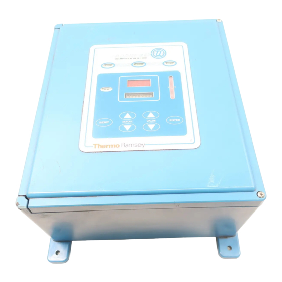
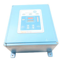
Tramp Metal Detector
Brand: Thermo Electron
|
Category: Metal Detector
|
Size: 3 MB
Table of Contents
Advertisement