
Subscribe to Our Youtube Channel
Summary of Contents for Thermo Electron Ramsey ORETRONIC III
- Page 1 Operating and Service Manual Ramsey ORETRONIC ™ Tramp Metal Detector R e c 41 05 R e v . E Pa rt No . 06 029 8...
- Page 2 O R E T R O N I C™ T r a m p M e t a l D e t e c t o r...
- Page 3 E l e c tron . I t ma y no t b e cop ied or reproduced in an y w a y w ithou t th e express wr itten consen t of Thermo Electron . Th is...
- Page 4 O R E T R O N I C™ T r a m p M e t a l D e t e c t o r Revision History Re vis ion A Ju ly, 2 000 Man ua l re le ased . Th is re vis io n d ocu men ts vers ion 1.01 of the ORETRONIC III Tramp Meta l Detec tor S o f tw a r e .
-
Page 5: Table Of Contents
Table of Contents T ab l e o f Con t en ts ....................i L i s t o f T ab le s . - Page 6 O R E T R O N I C™ T r a m p M e t a l D e t e c t o r 2.6 .5 F i e ld W ir in g th e T MD ..............2 -2 1 2.6 .5.1 Critical Wiring Co n d i t io n s .
- Page 7 O R E T R O N I C™ T r a m p M e t a l D e t e c t o r 3.2 .4.4.15 F ro n t P an e l T e s ts ..............3 -1 3 3.2 .4.4.16 So ftwar e V er s ion .
- Page 8 O R E T R O N I C™ T r a m p M e t a l D e t e c t o r B.6.1 . Input Powe r Requ ir e men ts ..............B -6 B.6.2 .
-
Page 9: List Of Tables
List of Tables T ab l e 2 -1 : SW 1 DIP Sw itch Settin g s ..............2-25 T ab l e 2 -2 : C PU Bo ard Sw itch Se ttin g s . - Page 10 O R E T R O N I C™ T r a m p M e t a l D e t e c t o r **** THIS PAGE LEFT BLANK INTENTIONALLY **** REC 4105...
-
Page 11: List Of Figures
List of Figures F ig u r e 1 -1 : M ag n e t i c Fie l d s Gen era t ed b y the T MD ..........1 -2 F ig u r e 1 - 2 : H o w Co n d u c t i v i t y A f f e c t s D ec a y T i me . - Page 12 O R E T R O N I C™ T r a m p M e t a l D e t e c t o r **** THIS PAGE LEFT BLANK INTENTIONALLY **** v iii REC 4105...
-
Page 13: About This Manual
It includes procedures for determining and correcting operational problems. Chapter 5: Service, Repair, and Replacement Parts tells you how to contact Thermo Electron service departments for assistance and how to order parts for your ORETRONIC III TMD. REC 4105 ix... -
Page 14: Documentation Conventions
O R E T R O N I C™ T r a m p M e t a l D e t e c t o r Appendix A: TMD Modbus Interface explains the implementation of Modbus protocol on the interface between the TMD and an intelligent host. Appendix B: Remote Front Panel describes the remote front panel option for the TMD. -
Page 15: Occupational Safety And Health Act (Osha)
Hence, Thermo Electron will not be responsible for meet- ing the full requirements of OSHA in respect to the equipment supplied or... -
Page 16: Thermo Electron Warranty
. Thermo Electron Warranty The seller agrees, represents, and warrants that the equipment delivered hereunder shall be free from defects in material and workmanship. Such warranty shall not apply to accessories, parts, or material purchased by the... -
Page 17: Disclaimer
Please note that Thermo Electron reserves the right to change and/or improve the product design and specifications without notice. - Page 18 **** THIS PAGE LEFT BLANK INTENTIONALLY **** x iv REC 4105...
-
Page 19: Overview
Chapter 1 Introduction to the ORETRONIC III Tramp Metal Detector This chapter introduces the ORETRONIC III Tramp Metal Detector (TMD). It gives an overview of the device’s capabilities, describes its basic functionality, and lists its technical specifications. Overview Tramp Metal Detector ( ) detects the presence of ORETRONI C I II T MD... -
Page 20: Figure 1-1: Magnetic Fields Generated By The Tmd
O R E T R O N I C™ T r a m p M e t a l D e t e c t o r Figure 1-1: Magnetic Fields Generated by the TMD PRIMARY MAGNETIC FIELD SECONDARY MAGNETIC FIELD TRAMP METAL... -
Page 21: Figure 1-3: Ore/Tramp Metal Decay Time Comparison
O R E T R O N I C™ T r a m p M e t a l D e t e c t o r Coal, aggregate, and mineral ores have conductivity characteristics con- siderably poorer than tramp metal, which means their magnetic field decays more quickly (see Figure 1-3). -
Page 22: System Components
O R E T R O N I C™ T r a m p M e t a l D e t e c t o r Figure 1-5: Signal Sensitivity/Measurement Timing Adjustments Because you can adjust signal sensitivity and measurement timing, you can set up the for optimal performance in your particular O RE T RO N I C I I I T MD... -
Page 23: Figure 1-6: Tmd System Components: Dual Coil
O R E T R O N I C™ T r a m p M e t a l D e t e c t o r Figure 1-6: TMD System Components: Dual Coil F l a g D r o p M a r k e r L i q u i d S p r a y M a r k e r Op t ion a l) B e a c o n a n d H o r n... -
Page 24: Support Structure And Coils
O R E T R O N I C™ T r a m p M e t a l D e t e c t o r Figure 1-7: TMD System Components: Under Belt Single Coil F l a g D r o p M a r k e r ( O p t i o n a l ) L i q u i d S p r a y M a r k e r ( O p t i o n a l ) B e a c o n a n d H o r n ( O p t i o n a l ) -
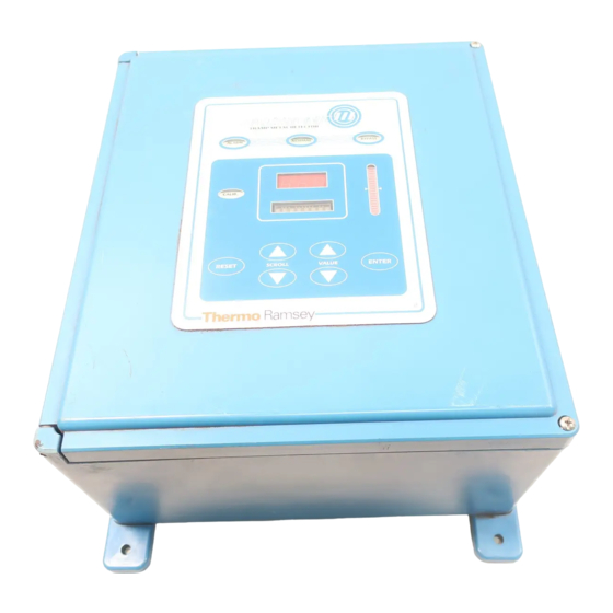
Page 25: Control Unit
O R E T R O N I C™ T r a m p M e t a l D e t e c t o r 1.3.2 Control Unit control unit is a microprocessor-based instrument that ORETRONI C I II provides excitation for the transmitter coil, accepts receiver coil signals, and annunciates the presence of tramp metal. -
Page 26: Remote Front Panel
O R E T R O N I C™ T r a m p M e t a l D e t e c t o r Optional high visibility indicators may be used to indicate NORMAL, BYPASS, and ALARM. This option is a light bar with bright incandescent lights that can be wired directly into the control electronics. -
Page 27: Technical Specifications
O R E T R O N I C™ T r a m p M e t a l D e t e c t o r into a convey or system can be found on the following Engineering Draw- ings in Appendix C of this manual: •... - Page 28 O R E T R O N I C™ T r a m p M e t a l D e t e c t o r 80 lb (36 kg) Enclosure (Control Unit) Type: NEMA 4X, non-metallic Size: 15.25 in. x 13.25 in. x 7.39 in. (H x W x D) (381 mm x 336 mm x 188 mm) Weight: 22 lb (10 kg)
- Page 29 O R E T R O N I C™ T r a m p M e t a l D e t e c t o r Maximum Non-Destructive Input Voltage: 150/275 VAC for one minute Overvoltage Category: Transient overvoltage according to installation category (Overvoltage Category II) Power Switch: On circuit board...
- Page 30 O R E T R O N I C™ T r a m p M e t a l D e t e c t o r Speed: Isolated Frequency range: 0.25–2,000 Hz (0.2 ms min. pulse width) 0.25–30 Hz (15 ms min. pulse width) Thresholds: 1.0 V min./3.0 V max.
- Page 31 O R E T R O N I C™ T r a m p M e t a l D e t e c t o r Bypass Indicator: Dry contact; 5 A, 250 VAC Power On Indicator: Dry contact; 5 A, 250 VAC Option: Dry contact;...
- Page 32 O R E T R O N I C™ T r a m p M e t a l D e t e c t o r **** THIS PAGE LEFT BLANK INTENTIONALLY **** 1-14 REC 4105...
-
Page 33: In S Ta L L In G The T
Chapter 2 Installing the TMD This chapter provides information about installing and setting up the ORETRONIC III TMD. It discusses installation considerations, provides procedures for mounting, and wiring, describes the hardware configuration, and provides procedures for determining initial setup parameters for the device. -
Page 34: Electrical Specifications
O R E T R O N I C™ T r a m p M e t a l D e t e c t o r • Metal deck plates or skirt boards located within 4 ft (1.2 m) either side of the coil support structure must be removed or replaced with non-metallic parts. -
Page 35: Equipment Handling
O R E T R O N I C™ T r a m p M e t a l D e t e c t o r in str u me nt dan ge rou s to life, limb, or property. CAUTION A ll w ir in g mu st be d on e in ac co rd anc e w ith f ie ld w ir in g... -
Page 36: Installing The Coil Support Structure And Coils For A Dual Coil Tmd
O R E T R O N I C™ T r a m p M e t a l D e t e c t o r This section provides procedures for installing the coil support structure and coils and for mounting and wiring the control unit. The installation procedures are different for dual coil and under belt single coil 2.6.1 Installing the Coil Support Structure and Coils for a... -
Page 37: In S Ta L L In G Sys T E M Dev I Ce
O R E T R O N I C™ T r a m p M e t a l D e t e c t o r Set the coil under the belt 1–2 in. (25.4–50.8 mm) below the belt line. The belt must not rub on the coil Mount the coil across the conveyor on the centerline between the two idlers Idler spacing at the coil location must be greater than 4 ft (1.2 m). - Page 38 O R E T R O N I C™ T r a m p M e t a l D e t e c t o r CAUTION M ak e s ur e t he m o un t in g s urfa ce i s f l at so t h at t he f iber g la ss e nc lo su re d oes not tw ist o r wa rp w he n t he m o unt i ng b o lt s ar e t i g ht e ne d .
-
Page 39: F I E Ld W Ir In G Th E T
O R E T R O N I C™ T r a m p M e t a l D e t e c t o r Figure 2-2: Control Unit Enclosure - Bottom View L ow V ol t ag e H ig h Vo lt ag e Co nn ect ion Co nn ect ion s... -
Page 40: F I E Ld W Ir In G Pro C Ed U R
O R E T R O N I C™ T r a m p M e t a l D e t e c t o r • Never use a “megger” to check the wiring. • A readily accessible disconnect device (maximum 20 A) shall be incorporated in the field wiring. -
Page 41: Con Ne Ct Ing In Com Ing Po We
O R E T R O N I C™ T r a m p M e t a l D e t e c t o r Route incoming connections at line voltages above 30 V through a conduit hole in the bottom right of the enclosure so that they are protected by the power cover (see Figure 2-2). - Page 42 O R E T R O N I C™ T r a m p M e t a l D e t e c t o r sufficient.) 4. Connect the wire to the safety ground terminal GROUND located on the right inside of the chassis. 2-24 REC 4105...
-
Page 43: Configuring The Tmd
O R E T R O N I C™ T r a m p M e t a l D e t e c t o r 5. Wire the input power to the 1 terminal labeled “ .” 6. Wire the input power to the 1 terminal labeled “... -
Page 44: C Pu Bo Ard Sw I T Ch Se T T In G
O R E T R O N I C™ T r a m p M e t a l D e t e c t o r 2.8.2 CPU Board Switch Settings Four switches on the board must be set for power, line voltage, and alarm output for the . -
Page 45: Initial Power On
O R E T R O N I C™ T r a m p M e t a l D e t e c t o r Note: Place SW2 (relay outputs) and SW3 (electronics) in the BYPASS position to disable alarms while setting up and calibrating the TMD. -
Page 46: Determining Values To Use For Initial Setup
O R E T R O N I C™ T r a m p M e t a l D e t e c t o r Press ENTER to set the digit. The next digit in the counter will be flashing. Repeat Steps 4 and 5 to enter each digit of the belt speed. -
Page 47: D E Ter Mi N I N G C L Ip D E L
O R E T R O N I C™ T r a m p M e t a l D e t e c t o r 2.11.2 Determining Clip Delay If your system uses a belt clip detector, you will need to know the distance between the clip detector and a point six inches past the receiver coil. -
Page 49: Operating The Tmd
Chapter 3 Operating the TMD This chapter provides information about setting up and operating the . The operator interface, including all keys, indicators, O RE T RO N I C I I I T MD and displays, is described. Procedures for initial setup and calibration are provided. -
Page 50: Operating Modes
O R E T R O N I C™ T r a m p M e t a l D e t e c t o r Figure 3-1: Tramp Metal Detector Front Panel 3.2.1 Operating Modes The TMD has two modes of operation: Run mode and Setup/Calibrate mode. N ORMAL When the TMD is in Run mode, the LED is lit, the display shows... -
Page 51: Figure 3-2: Tmd Menu Tree
O R E T R O N I C™ T r a m p M e t a l D e t e c t o r Figure 3-2: TMD Menu Tree C O U N T T M D i s i n n o r m a l R u n m o d e P S W D N / Y I f Y , p a s s w o r d i s r e q u i r e d C a l i b ? N / Y... -
Page 52: Scroll Keys
O R E T R O N I C™ T r a m p M e t a l D e t e c t o r Front Panel Keypad The keys on the TMD front panel are soft touch keys on a flat panel. The key s are used to set up and calibrate the TMD. -
Page 53: Reset Key
O R E T R O N I C™ T r a m p M e t a l D e t e c t o r 3.2.2.4 RESET Key RESET A LARM key is used to reset the output after metal detection. It also resets the coast count to zero. -
Page 54: Front Panel Displays
O R E T R O N I C™ T r a m p M e t a l D e t e c t o r 3.2.4 Front Panel Displays The front panel has two types of display indicators: an eight-character alphanumeric display and a three-digit counter LED. -
Page 55: Password Protection Screen
O R E T R O N I C™ T r a m p M e t a l D e t e c t o r 3.2.4.2 Password Protection Screen Password protection is used to restrict access to the setup and calibration settings. -
Page 56: Calibration Screens
O R E T R O N I C™ T r a m p M e t a l D e t e c t o r Note: To remove a forgotten password, set the and cycle DIP Switch the power. Set the back to and use the procedure above to define DIP Switch... -
Page 57: Calibrate For Clip
O R E T R O N I C™ T r a m p M e t a l D e t e c t o r EN T ER You can start auto-calibration by pressing the key without changing AUTO MET the value. -
Page 58: E St C A
O R E T R O N I C™ T r a m p M e t a l D e t e c t o r 3.2.4.3.4 EST Cal The next three screens are used to calibrate and test Electronically Simulated Tramp (EST). -
Page 59: Bar/Rod Length
O R E T R O N I C™ T r a m p M e t a l D e t e c t o r setting from 0 to 9. The larger the number, the more sensitive. If the setting is 0, the bar/rod option is disabled. Unlike calibrating for tramp metal and belt clips, calibrating for bar/rod detection is not automatic. -
Page 60: M A T Er I A L Cod
O R E T R O N I C™ T r a m p M e t a l D e t e c t o r 3.2.4.4.8 Material Code This screen is used to set the TMD measurement window timing. Window timing is based on a material type code from 0 to 7. -
Page 61: Switch Settings
O R E T R O N I C™ T r a m p M e t a l D e t e c t o r 3.2.4.4.14 Switch Settings These screens allow you to view the settings of the DIP Switches on the dis- play board (refer to Section 2.8.1 DIP Switch Settings) The display shows the switches in the following order. -
Page 62: E Rror M Es Sag
O R E T R O N I C™ T r a m p M e t a l D e t e c t o r 3.2.4.5 Error Messages The TMD has built-in error detecting that recognizes and reports error and fault conditions in the sy stem. -
Page 63: Setting Up The Tmd
O R E T R O N I C™ T r a m p M e t a l D e t e c t o r d ue to f au lt y w ir ing or ac tual fault c o n d i ti o n . -
Page 64: Using The Display Scroll
O R E T R O N I C™ T r a m p M e t a l D e t e c t o r 3.3.2 Using the Display Scroll When the TMD is in Setup/Calibrate mode, the display shows each individual variable that needs to be set up. -
Page 65: Initial Setup Procedure
O R E T R O N I C™ T r a m p M e t a l D e t e c t o r 3.3.4 Initial Setup Procedure Follow this procedure for the initial setup of the Tramp Metal Detector. Refer the Setup/Calibration Displays references in the left margin for the order of the display s used during setup. - Page 66 O R E T R O N I C™ T r a m p M e t a l D e t e c t o r If your system does not use a speed sensor, enter the belt speed in feet/minute. . (Refer to Section 2.11.1 Determining Belt Speed).
- Page 67 O R E T R O N I C™ T r a m p M e t a l D e t e c t o r Scroll to the CLP CORS display and press E N T ER (without changing the value) to start the coarse clip sensitivity auto- calibration.
- Page 68 O R E T R O N I C™ T r a m p M e t a l D e t e c t o r R E S ET will the alarm and zero the counter. Scroll to the EXIT? display and press EN TER This puts the in normal Run mode and saves...
-
Page 69: Maintaining And Troubleshooting
Chapter 4 Maintaining and Troubleshooting This chapter provides information about TMD maintenance and trouble- shooting. It includes pointers for routine maintenance and suggestions for diagnosing operational problems. The maintenance information in this chapter should be sufficient to meet your service needs. If you encounter a problem that requires technical assistance, please call your service representative (refer to Service and Repair Information... -
Page 70: Troubleshooting
O R E T R O N I C™ T r a m p M e t a l D e t e c t o r Troubleshooting If your is not detecting reliably or your calibrations are providing unexpected results, there are several things you can do to determine the cause of the problem. -
Page 71: Diagnosing And Correcting Problems
O R E T R O N I C™ T r a m p M e t a l D e t e c t o r 4.3.2 Diagnosing and Correcting Problems When you calibrate the TMD during initial setup, the microprocessor “imprints”... -
Page 72: False Tripping
O R E T R O N I C™ T r a m p M e t a l D e t e c t o r WARNING F a i lu re t o f o l lo w sa f e i nst a l la t i on a nd s e rv ic i ng p ro ce du res co u ld res u lt in de at h o r se r iou s in j ur y . - Page 73 O R E T R O N I C™ T r a m p M e t a l D e t e c t o r CAUTION K e ep hand s a nd c lo t h i ng a wa y f r o m al l m o v ing o r r ot at in g pa rts .
-
Page 74: Finding The Source Of Mechanical Or Electrical Noise
O R E T R O N I C™ T r a m p M e t a l D e t e c t o r For a single coil T MD • Loosen the plastic bolts that hold the coil to the frame. - Page 75 O R E T R O N I C™ T r a m p M e t a l D e t e c t o r Follow this procedure to find the source of mechanical or electrical noise. Balance the coils as evenly as possible using the procedure from 4.4.1 Correcting Coil Imbalance.
- Page 76 O R E T R O N I C™ T r a m p M e t a l D e t e c t o r If the noise level increases when the conveyor is run empty and mechanical vibrations do not appear to be the problem, the problem may be electrical noise from the conveyor motor or electrical wiring from the motor.
-
Page 77: Adjusting For High Product Noise (Mineral Ores)
O R E T R O N I C™ T r a m p M e t a l D e t e c t o r Observe the bar graph. If the number of s lit decreases, this is a better operating frequency for the . - Page 78 O R E T R O N I C™ T r a m p M e t a l D e t e c t o r Follow this procedure to adjust the sensitivity of the for mineral ores. Balance the coils as evenly as possible using the procedure from 4.4.1 Correcting Coil Imbalance.
-
Page 79: Adjusting For Bar/Rod Detection
O R E T R O N I C™ T r a m p M e t a l D e t e c t o r 4.4.4 Adjusting for Bar/Rod Detection The TMD bar/rod detection option allows you to set a specific sensitivity calibration for bars or rods that are small in diameter and one to ten feet in length. - Page 80 O R E T R O N I C™ T r a m p M e t a l D e t e c t o r Make sure you have correctly determined the clip delay, which is designed to prevent the TMD from tripping when a clip goes through.
- Page 81 O R E T R O N I C™ T r a m p M e t a l D e t e c t o r WARNING H ig h v o ltag e t h at ma y be pr es ent on lea ds c ou l d c aus e e l ect r ica l s ho ck .
- Page 82 O R E T R O N I C™ T r a m p M e t a l D e t e c t o r Follow this procedure to adjust the clip sensitivity. CLP CORS Scroll to the display and record the clip coarse sensitivity value shown in the counter.
-
Page 83: Pa S Si Ng T Ra M P U Nd Ete Ct
O R E T R O N I C™ T r a m p M e t a l D e t e c t o r Run the conveyor and watch for false trips. CLP FINE If no false trips occur, the value is set correctly. -
Page 84: Adjusting Metal Sensitivity
O R E T R O N I C™ T r a m p M e t a l D e t e c t o r 4.5.1 Adjusting Metal Sensitivity The most common cause of undetected tramp is having the metal sensitivity setting too low for the tramp you are trying to detect. -
Page 85: C H Ang In G The Ma T Er I A L T Yp E Cod E To Adj U S T S En Si T Iv I T
O R E T R O N I C™ T r a m p M e t a l D e t e c t o r To manually adjust the metal sensitivity values, place the TMD in FINE Calibrate mode and scroll to the display. -
Page 86: T E S T In G For C O I L O R Jun Ct I O N Bo X D Ama G
O R E T R O N I C™ T r a m p M e t a l D e t e c t o r First, you must determine how well the TMD is working with the current material type code (which should be 3). -
Page 87: F Ig U R E 4 -1 : Te R Mi N Als O N Th E Cpu B Oa
O R E T R O N I C™ T r a m p M e t a l D e t e c t o r WARNING F a i lu re f o l lo w sa f e ins t a l lat i on a nd s er v ic in g p ro ced u res c ou l d res u lt i n dea t h... -
Page 88: Testing The Transmitter Coil
O R E T R O N I C™ T r a m p M e t a l D e t e c t o r 4.5.3.1 Testing the Transmitter Coil Follow this procedure to test the transmitter coil if your sy stem does not have a junction box. -
Page 89: Determining Tmd Malfunction
O R E T R O N I C™ T r a m p M e t a l D e t e c t o r If your system uses a junction box, follow this procedure to test the receiver coil. - Page 90 O R E T R O N I C™ T r a m p M e t a l D e t e c t o r 1. Turn on power to the control unit (SW6). 2. If the display s do not light, check power wiring on TB1. 3.
- Page 91 O R E T R O N I C™ T r a m p M e t a l D e t e c t o r The basic procedure for testing components is: Turn the power switch (SW6) off. Wire in a component.
-
Page 92: Pa S Si Ng Bar S O R Ro Ds Un De Te Ct
O R E T R O N I C™ T r a m p M e t a l D e t e c t o r 14. Pass a large piece of tramp or steel (3 inches or more in diameter) through the coils while watching the bar graph. -
Page 93: Installing Default Values
O R E T R O N I C™ T r a m p M e t a l D e t e c t o r Installing Default Values If the TMD software should become corrupted, you may need to install the factory default values to get your sy stem running. -
Page 94: E R Ro R M Es Sa G
O R E T R O N I C™ T r a m p M e t a l D e t e c t o r Error Messages The TMD has built-in error detecting that recognizes and reports error and fault conditions in the sy stem. -
Page 95: T Ab L E 4 -2 : F Au Lt M Es Sag
O R E T R O N I C™ T r a m p M e t a l D e t e c t o r Table 4-2: Fault Messages MESSAGE MEAN IN G In dic a tes an ope n or sh or t c ircu i t XMIT FLT h as be en de tec ted in th e t r a ns m i t ter c o i l . - Page 96 O R E T R O N I C™ T r a m p M e t a l D e t e c t o r **** THIS PAGE LEFT INTENTIONALLY BLANK **** R E C 4 1 0 5 4-28...
-
Page 97: Service And Repair Information
Contact the Field Service department at the number given below for current rates and scheduling. Thermo Electron has a repair center located at our plant in Minneapolis, Minnesota. Products that need system checkout or repair can be returned to... -
Page 98: Parts Lists
Purchase Order number • Date required • Preferred shipping method • Part number(s), description, and quantity needed Telephone or FAX: Thermo Electron Customer Service Department 501 90th Ave. NW Minneapolis, MN 55433 FAX: (763) 780-2525 Customers A through I (763) 783-2775... - Page 99 O R E T R O N I C™ T r a m p M e t a l D e t e c t o r 501 90 Avenue N.W . Minn eapo lis R e t u r n M a t e r i a l A u t h o r i z a t i o n 763 783 2500 RMA No.
-
Page 100: Disposal Of Hazardous Waste
All soldered printed circuit boards must be disposed of in accordance with your local Hazardous Waste policy . As an alternative, you may return product supplied by Thermo Electron, with an RMA form, freight prepaid for disposal. Contact our Repair and Returns department at (763) 783-2774 to get an RMA number to use on the form. -
Page 101: Appendix Atmd Modbus Interface
Appendix A TMD Modbus Interface This Appendix provides information about the Modbus protocol implemented for communications between the ORETRONIC III Tramp Metal Detector (TMD) and an intelligent host or PLC. It deals only with the protocol as used for this particular interface. If you need detailed information about all aspects of Modbus protocol, refer to Modicon‚... -
Page 102: Example: Read Holding Registers
O R E T R O N I C™ T r a m p M e t a l D e t e c t o r Broadcast messages are not supported in this implementation. Following are examples of Modbus query messages and their responses. A.2.1. -
Page 103: Example: Preset Multiple Registers
O R E T R O N I C™ T r a m p M e t a l D e t e c t o r A.2.2. Example: Preset Multiple Registers In this example, the host writes new data (00 0A and 01 02 hex) to holding registers 40002–40003 in slave device 7. -
Page 104: Master/Slave Timing Considerations
O R E T R O N I C™ T r a m p M e t a l D e t e c t o r A.2.4. Master/Slave Timing Considerations The Modicon Modbus protocol establishes a minimum timing interval between query and response messages that use RTU framing. -
Page 105: Table A-2: Tmd Holding Registers (Continued)
O R E T R O N I C™ T r a m p M e t a l D e t e c t o r Table A-2: TMD Holding Registers (Continued) R E G I S T E R A C C E S S T Y P E D E S C R I P T I O N... - Page 106 O R E T R O N I C™ T r a m p M e t a l D e t e c t o r R E G I S T E R A C C E S S T Y P E D E S C R I P T I O N A D D R E S S...
- Page 107 O R E T R O N I C™ T r a m p M e t a l D e t e c t o r R E G I S T E R A C C E S S T Y P E D E S C R I P T I O N A D D R E S S...
- Page 108 O R E T R O N I C™ T r a m p M e t a l D e t e c t o r R E G I S T E R A C C E S S T Y P E D E S C R I P T I O N A D D R E S S...
- Page 109 O R E T R O N I C™ T r a m p M e t a l D e t e c t o r R E G I S T E R A C C E S S T Y P E D E S C R I P T I O N A D D R E S S...
- Page 110 O R E T R O N I C™ T r a m p M e t a l D e t e c t o r **** THIS PAGE LEFT BLANK INTENTIONALLY **** R E C 4 1 0 5 A-10...
-
Page 111: Appendix B Remote Front Panel
Appendix B Remote Front Panel This Appendix describes the optional remote front panel for the ORETRONIC III TMD. It includes technical specifications, wiring procedures, instructions for setup and operation, and a spare parts list. B.1. Overview The operator interface to the TMD is a front panel on the control unit. The front panel is composed of a touch panel keypad, LED indicators, an eight- character alphanumeric display, and a three-digit counter LED. -
Page 112: Technical Specifications
O r e t r o n i c ™ I I I T r a m p M e t a l D e t e c t o r B.3. Technical Specifications This section lists the technical specifications that pertain to the remote front panel of an ORETRONIC III Tramp Metal Detector. -
Page 113: Installing The Remote Front Panel
O r e t r o n i c I I I T r a m p M e t a l D e t e c t o r Maximum Non-Destructive Input Voltage: 150/300 VAC for one minute Overvoltage Category: Transient overvoltage according to installation category (Overvoltage Category II) Power Switch:... -
Page 114: Mounting The Remote Front Panel
O r e t r o n i c ™ I I I T r a m p M e t a l D e t e c t o r WARNING H ig h v ol t a ge t hat m a y be p re se nt on l e ad s co u ld ca use e le ct r i ca l s ho ck . -
Page 115: Figure B-1: Remote Front Panel Dimensions
O r e t r o n i c I I I T r a m p M e t a l D e t e c t o r Figure B-1: Remote Front Panel Dimensions A 9 0 5 1 4 WARNING M ak e s ure t he m ou nt i ng su rfac e is f l at s o t hat t he f i b er g las s e nc l osu re d o es not... -
Page 116: Field Wiring The Remote Front Panel
O r e t r o n i c ™ I I I T r a m p M e t a l D e t e c t o r Follow this procedure to mount the remote front panel enclosure. Open the enclosure door. -
Page 117: Field Wiring Procedure
O r e t r o n i c I I I T r a m p M e t a l D e t e c t o r • Connect the shield only where shown. • Never use a “megger” to check the wiring. •... -
Page 118: Setting The Comm Switches
O r e t r o n i c ™ I I I T r a m p M e t a l D e t e c t o r 21. Connect the communications cables to the appropriate terminals on the remote front panel chassis cover (see Figure B-2). -
Page 119: Setting Up And Operating The Remote Front Panel
O r e t r o n i c I I I T r a m p M e t a l D e t e c t o r Table B-3: Comm Switch Settings P O S F U N C T I O N O F F 1 &... - Page 120 O r e t r o n i c ™ I I I T r a m p M e t a l D e t e c t o r **** THIS PAGE LEFT BLANK INTENTIONALLY **** R E C 4 1 0 5 B-10...
-
Page 121: Overview
Appendix C Electronically Simulated Tramp (EST) C.1. Overview This appendix introduces you to Electronically Simulated Tramp (EST), a specially designed option al sy stem for your TMD. EST works as a quality assurance check for your TMD to ensure the transmitter and receiver coils are operating properly. -
Page 122: Electrical Installation
O r e t r o n i c ™ I I I T r a m p M e t a l D e t e c t o r C.4. Electrical Installation See Appendix D for the engineering drawing related to electrical installation. C.5. -
Page 123: Last Est (Est Last)
O r e t r o n i c ™ I I I T r a m p M e t a l D e t e c t o r C.6.1. Last EST (EST Last) Last EST (EST LAST) displays the last signal reading for the last interval EST test. - Page 124 O r e t r o n i c ™ I I I T r a m p M e t a l D e t e c t o r **** THIS PAGE LEFT INTENTIONALLY BLANK **** R E C 4 1 0 5...
-
Page 125: Appendix D Engineering Drawings
Appendix D Engineering Drawings This Appendix contains the engineering drawings for your O RETRONI C III Tramp Metal Detector sy stem. The following drawings are included: Field Wiring Diagram (D07328C-E201) Under Belt Single Coil Assembly Stand (D07328C-A110-XX) Under Belt Single Coil Final Assembly (D07328C-A101) Under Belt Single Coil Installation Placement (D07328C-A102) - Page 126 O r e t r o n i c ™ I I I T r a m p M e t a l D e t e c t o r Electronically Simulated Tramp (EST) Assembly Standard/Hi Strength (D07328C-K001) EST Outline and Mounting (D07328C-B008) EST Under Belt Outline and Mounting (D07328C-B102)
-
Page 127: Index
Index b e l t sp e ed ......................2 -2 7 c a l ibr a t io n s p e ed sen so r . - Page 128 O r e t r o n i c ™ I I I T r a m p M e t a l D e t e c t o r a u d i t in t ....................S e e E ST b ar /ro d l en g th .
Need help?
Do you have a question about the Ramsey ORETRONIC III and is the answer not in the manual?
Questions and answers