Sign In
Upload
Manuals
Brands
Texas Instruments Manuals
Media Converter
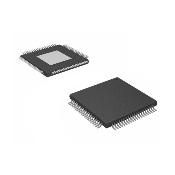
TVP5147M1PFP
User Manuals: Texas Instruments TVP5147M1PFP Decoder
Manuals and User Guides for Texas Instruments TVP5147M1PFP Decoder. We have
1
Texas Instruments TVP5147M1PFP Decoder manual available for free PDF download: Data Manual
Texas Instruments TVP5147M1PFP Data Manual (100 pages)
NTSC/PAL/SECAM 2x10-Bit Digital Video Decoder With Macrovision Detection, YPbPr Inputs, and 5-Line Comb Filter
Brand:
Texas Instruments
| Category:
Media Converter
| Size: 1 MB
Table of Contents
Table of Contents
3
Section Page
6
List of Tables
8
1 Introduction
9
Detailed Functionality
10
TVP5147M1 Applications
11
Related Products
11
Ordering Information
11
Functional Block Diagram
12
Terminal Assignments
13
Terminal Assignments Diagram
13
Terminal Functions
14
2 Functional Description
17
Analog Processing and A/D Converters
17
Video Input Switch Control
17
Analog Processors and A/D Converters
17
Analog Input Clamping
18
Automatic Gain Control
18
Analog Video Output
18
A/D Converters
18
Digital Video Processing
19
Decimation Filter
19
Composite Processor
19
Digital Video Processing Block Diagram
19
Composite and S-Video Processing Block Diagram
20
Color Low-Pass Filter with Filter Characteristics, NTSC/PAL ITU-R BT.601 Sampling
21
Color Low-Pass Filter Frequency Response
21
Chroma Trap Filter Frequency Response, NTSC ITU-R BT.601 Sampling
21
Chroma Trap Filter Frequency Response, PAL ITU-R BT.601 Sampling
21
Luminance Processing
22
Color Transient Improvement
22
Luminance Edge-Enhancer Peaking Block Diagram
22
Peaking Filter Response, NTSC/PAL ITU-R BT.601 Sampling
22
Clock Circuits
23
Real-Time Control (RTC)
23
Output Formatter
23
Output Format
23
Reference Clock Configurations
23
RTC Timing
23
Separate Syncs
24
Summary of Line Frequencies, Data Rates, and Pixel/Line Counts
24
Vertical Synchronization Signals for 525-Line System
25
Vertical Synchronization Signals for 625-Line System
26
Horizontal Synchronization Signals for 10-Bit 4:2:2 Mode
27
Horizontal Synchronization Signals for 20-Bit 4:2:2 Mode
28
Embedded Syncs
29
I 2 C Host Interface
29
EAV and SAV Sequence
29
VSYNC Position with Respect to HSYNC
29
I 2 C Host Interface Terminal Description
30
I 2 C Operation
30
Reset and I C Bus Address Selection
30
VBUS Access
30
VBUS Access
31
VBI Data Processor
32
Supported VBI System
32
Ancillary Data Format and Sequence
33
VBI FIFO and Ancillary Data in Video Stream
33
VBI Raw Data Output
34
Reset and Initialization
34
Reset Timing
34
VBI Raw Data Output Format
34
Reset Sequence
34
Adjusting External Syncs
35
Internal Control Registers
35
C Register Summary
35
VBUS Register Summary
38
Register Definitions
39
Input Select Register
39
Analog Channel and Video Mode Selection
39
AFE Gain Control Register
40
Video Standard Register
40
Operation Mode Register
41
Autoswitch Mask Register
41
Color Killer Register
42
Luminance Processing Control 1 Register
42
Luminance Processing Control 2 Register
43
Luminance Processing Control 3 Register
43
Luminance Brightness Register
43
Chrominance Processing Control 1 Register
44
Chrominance Saturation Register
44
Luminance Contrast Register
44
Chroma Hue Register
44
Chrominance Processing Control 2 Register
45
AVID Start Pixel Register
45
HSYNC Start Pixel Register
46
HSYNC Stop Pixel Register
46
VSYNC Start Line Register
46
AVID Stop Pixel Register
46
VSYNC Stop Line Register
47
VBLK Start Line Register
47
VBLK Stop Line Register
47
CTI Delay Register
47
Sync Control Register
48
CTI Control Register
48
Output Formatter 1 Register
49
Output Formatter 2 Register
49
Output Formatter 3 Register
50
Output Formatter 4 Register
51
Output Formatter 5 Register
52
Clear Lost Lock Detect Register
53
Output Formatter 6 Register
53
Status 1 Register
54
AGC Gain Status Register
55
Status 2 Register
55
Video Standard Status Register
56
GPIO Input 1 Register
56
GPIO Input 2 Register
57
AFE Coarse Gain for CH 1 Register
58
AFE Coarse Gain for CH 2 Register
58
AFE Coarse Gain for CH 3 Register
59
AFE Coarse Gain for CH 4 Register
59
AFE Fine Gain for Y_Chroma Register
60
AFE Fine Gain for Pb Register
60
AFE Fine Gain for Pr Register
60
AFE Fine Gain for Cvbs_Luma Register
61
Field ID Control Register
61
F-Bit and V-Bit Control 1 Register
62
AGC Decrement Speed Control Register
63
Back-End AGC Control Register
63
ROM Version Register
63
AGC White Peak Processing Register
64
F and V Bit Control Register
65
Horizontal Shake Increment Register
66
VCR Trick Mode Control Register
66
AGC Increment Speed Register
66
AGC Increment Delay Register
66
Analog Output Control 1 Register
67
CPLL Speed Control Register
67
Chip ID MSB Register
67
Chip ID LSB Register
67
Vertical Line Count Register
68
AGC Decrement Delay Register
68
Status Request Register
68
VDP TTX Filter and Mask Registers
69
VDP TTX Filter Control Register
70
VDP FIFO Word Count Register
71
Teletext Filter Function
71
VDP FIFO Interrupt Threshold Register
72
VDP Line Number Interrupt Register
72
VDP FIFO Output Control Register
72
VDP FIFO Reset Register
72
VDP Pixel Alignment Register
73
VDP Global Line Mode Register
73
VDP Line Start Register
73
VDP Line Stop Register
73
VBUS Data Access with no VBUS Address Increment Register
74
VBUS Data Access with VBUS Address Increment Register
74
VDP Full Field Enable Register
74
VDP Full Field Mode Register
74
Interrupt Raw Status 0 Register
75
VBUS Address Access Register
75
FIFO Read Data Register
75
Interrupt Raw Status 1 Register
76
Interrupt Status 0 Register
76
Interrupt Status 1 Register
77
Interrupt Mask 0 Register
78
Interrupt Clear 0 Register
79
Interrupt Mask 1 Register
79
Interrupt Clear 1 Register
80
VDP Closed Caption Data Register
81
VBUS Register Definitions
81
VDP WSS Data Register
81
VDP V-Chip TV Rating Block 1 Register
82
VDP V-Chip TV Rating Block 2 Register
82
VDP VITC Data Register
82
VDP V-Chip TV Rating Block 3 Register
83
VDP V-CHIP MPAA Rating Data Register
83
VDP General Line Mode and Line Address Register
84
VDP Vps/Gemstar Data Register
85
Interrupt Configuration Register
86
Analog Output Control 2 Register
86
Recommended Operating Conditions
87
3 Electrical Specifications
87
Absolute Maximum Ratings
87
Crystal Specifications
87
Electrical Characteristics
88
Clocks, Video Data, and Sync Timing
89
I 2 C Host Port Timing
89
Example 1
91
Example 2
91
Recommended Settings
91
Application Information
95
Application Example
95
I2C Address Selection
95
Example Application Circuit
95
Packaging Information
97
Advertisement
Advertisement
Related Products
Texas Instruments TVP5154A
Texas Instruments TVP5151
Texas Instruments TMS320DM365 EVM
Texas Instruments THS1031
Texas Instruments TPS61092
Texas Instruments TPS543C20EVM-054
Texas Instruments TLV2542EVM
Texas Instruments TPS61032EVM-208
Texas Instruments TPS53319EVM-136
Texas Instruments TPS548D21EVM-784
Texas Instruments Categories
Motherboard
Control Unit
Microcontrollers
Computer Hardware
Calculator
More Texas Instruments Manuals
Login
Sign In
OR
Sign in with Facebook
Sign in with Google
Upload manual
Upload from disk
Upload from URL