Sign In
Upload
Manuals
Brands
Texas Instruments Manuals
Motherboard
TPS92520EVM-133
Texas Instruments TPS92520EVM-133 Manuals
Manuals and User Guides for Texas Instruments TPS92520EVM-133. We have
1
Texas Instruments TPS92520EVM-133 manual available for free PDF download: User Manual
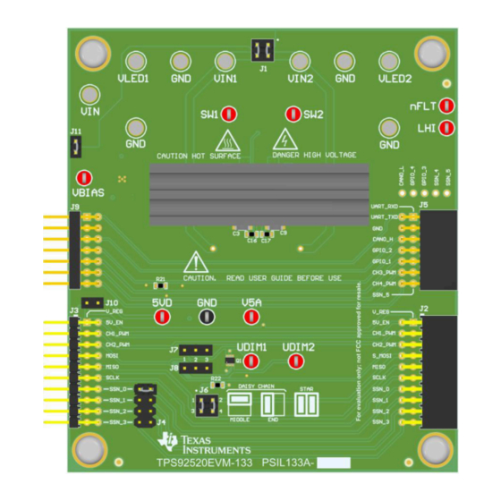
Texas Instruments TPS92520EVM-133 User Manual (57 pages)
Dual 1.6-A Synchronous Buck LED Driver Evaluation Module
Brand:
Texas Instruments
| Category:
Motherboard
| Size: 7.62 MB
Table of Contents
Table of Contents
1
General Texas Instruments High Voltage Evaluation (TI HV EMV) User Safety Guidelines
3
Description
5
Typical Applications
5
Warnings
5
Connector Description
5
Figure 1-1. Connection Diagram of Computer, USB Cable, LEDMCUEVM-132, and TPS92520EVM-133
6
Table 1-1. Connector Descriptions
6
Table 1-2. Test Points
7
Performance Specifications
8
Table 2-1. TPS92520EVM Performance Specifications
8
Performance Data and Typical Characteristic Curves
9
A CC BUCK SW-Node Voltage Waveform
9
Start-Up Waveforms
10
PWM Dimming
10
Schematic, PCB Layout, and Bill of Materials
10
Schematic
11
Figure 4-1. TPS92520EVM-133 Schematic
12
Figure 4-2. TPS92520EVM-133 Schematic
12
Layout
13
Figure 4-3. TPS92520EVM-133 Assembly
13
Figure 4-4. TPS92520EVM-133 Top Layer and Top Overlay
14
Figure 4-5. TPS92520EVM-133 Inner-Layer 1
14
Figure 4-6. TPS92520EVM-133 Inner-Layer 2
15
Figure 4-7. TPS92520EVM-133 Bottom Layer and Bottom Overlay
15
Bill of Materials
16
Table 4-1. TPS92520EVM-133 Bill of Materials
16
Software
19
Demonstration Kit Software Installation for LEDMCUEVM-132 Board
19
Step-By-Step Installation Instructions
19
Figure 5-1. Setup Screen 1
19
Figure 5-2. Setup Screen 2
20
Figure 5-3. Setup Screen 3
20
Figure 5-4. Setup Screen 4
21
Figure 5-5. Setup Screen 5
21
Figure 5-6. Setup Screen 6
22
Figure 5-7. Setup Screen 7
22
Figure 5-8. Setup Screen 8
23
Figure 5-9. Setup Screen 9
23
Figure 5-10. Setup Screen 10
24
Figure 5-11. Setup Screen 11
24
Figure 5-12. Setup Screen 12
25
Figure 5-13. Setup Screen 13
25
Figure 5-14. Setup Screen 14
26
Figure 5-15. Setup Screen 15
26
Figure 5-16. Setup Screen 16
27
Figure 5-17. Setup Screen 17
27
Figure 5-18. Setup Screen 18
28
Installation Error Recovery
29
Figure 5-19. Setup Screen 19
29
Checking for Updates
30
Figure 5-20. Help Menu and Checking for Updates
30
Figure 5-21. Update Screen 1
30
Figure 5-22. Update Screen 2
31
Figure 5-23. J15 Jumper and RESET_SW1 Switch for Bootloader Mode
31
Figure 5-24. Setup Screen 5
32
Figure 5-25. Setup Screen 6
32
Figure 5-26. 15 Jumper and RESET_SW1 Switch for Normal Mode
33
TPS92520EVM-133 Power up and Operation
34
Figure 6-1. LEDMCUEVM-132 Connection to TPS92520EVM-133
34
Figure 6-2. GUI Setup Screen 1
35
Figure 6-3. GUI Setup Screen 2
35
Figure 6-4. TPS92520 - EVM133 GUI Start-Up
36
MCU Control Window
37
Figure 6-5. MCU Control (External PWM) Window
37
Figure 6-6. External PWM Hardware
37
SPI Command Window
38
Figure 6-7. SPI Command Window
38
Figure 6-8. SPI Read Example
39
Watchdog Window
40
Figure 6-9. SPI Write Example
40
Figure 6-10. Watchdog Settings Window
40
Figure 6-11. no Watch Dog Timer Is
40
Figure 6-12. GUI after the "En 520 no WD" Button Is Selected
41
GUI Devices Window
42
Figure 6-13. Device Command Window
42
Figure 6-14. Devices Window after Watchdog Is
43
Figure 6-15. Channel 1 Window - Configurations, Measurement, and Fault Window
44
Figure 6-16. Analog Current Slide Bar
44
Figure 6-17. on Time Slide Bar for Changing Switching Frequency
45
Figure 6-18. Internal PWM Duty Cycle Slide Bar
45
Figure 6-19. Channel Feature Selection
45
Figure 6-20. VIN and LED Voltage Measurements from Internal ADC
46
Figure 6-21. Status Indicators for Channels
46
Figure 6-22. Device Window - Channel and Systems Voltage Measurements
47
Figure 6-23. Temperature, V5D Measurement, and TW Setpoint
47
Figure 6-24. Internal PWM Frequency Set-Point, Sleep Mode, Reading Registers, and Limp Home Mode
48
Figure 6-25. Fault Timer, Flags, and Resetting of Faults
48
Limp Home Mode Window
49
Figure 6-26. GUI, Limp Home Mode Window
49
Figure 6-27. Example Limp Home Mode Settings
50
Advertisement
Advertisement
Related Products
Texas Instruments TPS92520-Q1
Texas Instruments TPS92520EVM-074
Texas Instruments TPS92518EVM
Texas Instruments TPS92515HVEVM-749
Texas Instruments TPS92830-Q1
Texas Instruments TPS92611-Q1
Texas Instruments TPS92611EVM
Texas Instruments TPS92612-Q1
Texas Instruments TPS92682EVM
Texas Instruments TPS92691
Texas Instruments Categories
Motherboard
Control Unit
Microcontrollers
Computer Hardware
Calculator
More Texas Instruments Manuals
Login
Sign In
OR
Sign in with Facebook
Sign in with Google
Upload manual
Upload from disk
Upload from URL