Sign In
Upload
Manuals
Brands
Texas Instruments Manuals
Motherboard
TPR12REVM
Texas Instruments TPR12REVM Manuals
Manuals and User Guides for Texas Instruments TPR12REVM. We have
1
Texas Instruments TPR12REVM manual available for free PDF download: User Manual
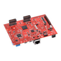
Texas Instruments TPR12REVM User Manual (43 pages)
Evaluation Module
Brand:
Texas Instruments
| Category:
Motherboard
| Size: 2 MB
Table of Contents
Description
1
Features
1
Table of Contents
2
1 Evaluation Module Overview
4
Introduction
4
Preface: Read this First
4
Kit Overview
4
Figure 1-1. Am273X EVM Top Component Identification
5
Figure 1-2. Am273X EVM Bottom Component Identification
6
Figure 1-3. Interfacing DCA1000 EVM to Debug Connector of the Am273X EVM
7
Figure 1-4. Security Field Parameter
8
2 Hardware
9
Board Setup
9
Figure 2-1. Barrel Jack Connector (J12)
9
Table 2-1. Power Status Led's
9
Figure 2-2. Am273X EVM Push Buttons
10
Table 2-2. EVM Push Buttons
10
Table 2-3. Push Buttons Switches Information
10
Figure 2-3. Am273X EVM Switches
11
Table 2-4. Switches Information
11
Figure 2-4. Am273X EVM Leds
12
Table 2-5. LED Information
13
Hardware Description
14
Figure 2-5. SOP Jumpers
14
Figure 2-6. Am273X Functional Block Diagram
14
Table 2-6. Boot Mode Selection Table
14
Figure 2-7. QSPI Interface
15
Figure 2-8. Board ID EEPROM
15
Figure 2-9. Ethernet Interface Block Diagram
16
Figure 2-10. Ethernet PHY Schematic
16
Figure 2-11. RJ45 Connector
17
Figure 2-12. FTDI USB Block Diagram
18
Figure 2-13. FTDI USB Connector
19
Figure 2-14. XDS USB Interface Block Diagram
19
Figure 2-15. XDS USB Connector
20
Figure 2-16. MSS_I2CA Block Diagram
21
Figure 2-17. UART Interface
23
Figure 2-18. CAN-A Interface Block Diagram
24
Figure 2-19. CAN-A Schematic
24
Figure 2-20. CAN-B Interface Block Diagram
25
Figure 2-21. CAN-B Schematic
25
Figure 2-22. JTAG Emulation Block Diagram
26
Figure 2-23. MSS SPI Interface
27
Connectors
28
Figure 2-24. Epwm Debug Header Pin
28
Figure 2-25. High Density FE Connector-1
28
Figure 2-26. High Density FE Connector-2
30
Figure 2-27. MIPI 60 Connector Schematic
32
Figure 2-28. Debug Connector Schematic
33
Mechanical Mounting of the PCB
35
Figure 2-29. Am273X EVM Mechanical Assembly
35
Figure 2-31. Am273X EVM Interfaced to the DCA1000 EVM
35
3 Additional Information
36
Trademarks
36
A Rev. C Design Changes
36
4 Revision History
37
Evm
42
Advertisement
Advertisement
Related Products
Texas Instruments TPSM8D6C24
Texas Instruments TPA6043A4
Texas Instruments TPS562231EVM
Texas Instruments TPS55289-Q1
Texas Instruments TPS62400
Texas Instruments TPS62290EVM-279
Texas Instruments TPS53667EVM-769
Texas Instruments TPS5210EVM-116
Texas Instruments eFuse TPS25983EVM
Texas Instruments TPS658 EVM Series
Texas Instruments Categories
Motherboard
Control Unit
Microcontrollers
Computer Hardware
Calculator
More Texas Instruments Manuals
Login
Sign In
OR
Sign in with Facebook
Sign in with Google
Upload manual
Upload from disk
Upload from URL