Sign In
Upload
Manuals
Brands
Texas Instruments Manuals
Microcontrollers
MSP430G2231
Texas Instruments MSP430G2231 Manuals
Manuals and User Guides for Texas Instruments MSP430G2231. We have
1
Texas Instruments MSP430G2231 manual available for free PDF download: User Manual
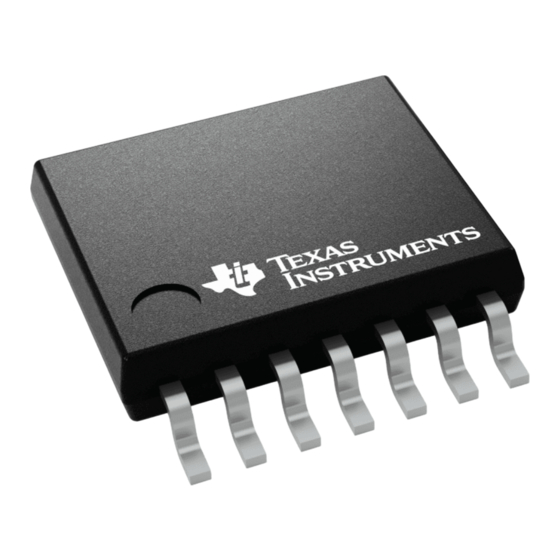
Texas Instruments MSP430G2231 User Manual (54 pages)
Automotive Mixed-Signal Microcontroller
Brand:
Texas Instruments
| Category:
Microcontrollers
| Size: 1 MB
Table of Contents
Table of Contents
3
1 Features
4
2 Applications
4
3 Description
4
4 Functional Block Diagram
4
5 Revision History
4
6 Device Characteristics
4
7 Terminal Configuration and Functions
5
14-Pin PW Package (Top View)
5
16-Pin RSA Package (Top View)
5
Terminal Functions
6
8 Detailed Description
7
Cpu
7
Instruction Set
7
Operating Modes
8
Interrupt Vector Addresses
9
Special Function Registers (Sfrs)
10
Memory Organization
11
Flash Memory
11
Peripherals
12
9 Specifications
16
Absolute Maximum Ratings
16
Recommended Operating Conditions
16
Active Mode Supply Current into
17
Excluding External Current
17
Typical Characteristics - Active Mode Supply Current
17
Excluding External Current
18
Typical Characteristics, Low-Power Mode Supply Currents
18
Schmitt-Trigger Inputs - Ports Px
19
Leakage Current - Ports Px
19
Outputs - Ports Px
19
Output Frequency - Ports Px
19
Typical Characteristics - Outputs
20
Por, Bor
21
Main DCO Characteristics
23
DCO Frequency
23
Calibrated DCO Frequencies - Tolerance
24
Wakeup from Lower-Power Modes (LPM3, LPM4) - Electrical Characteristics
24
Typical Characteristics - DCO Clock Wakeup Time from LPM3, LPM4
24
Crystal Oscillator, Xt1, Low-Frequency Mode
25
Internal Very-Low-Power Low-Frequency Oscillator (VLO)
25
Timer_A
25
USI, Universal Serial Interface
26
Typical Characteristics - USI Low-Level Output Voltage on SDA and SCL
26
10-Bit ADC, Power Supply and Input Range Conditions
27
10-Bit ADC, Built-In Voltage Reference
28
10-Bit ADC, External Reference
29
10-Bit ADC, Timing Parameters
29
10-Bit ADC, Linearity Parameters
29
10-Bit ADC, Temperature Sensor and Built-In
30
Flash Memory
30
JTAG and Spy-Bi-Wire Interface
31
10 I/O Port Schematics
32
Port P1 Pin Schematic: P1.0 to P1.2, Input/Output with Schmitt Trigger
33
Port P1 Pin Schematic: P1.3, Input/Output with
34
Port P1 Pin Schematic: P1.4, Input/Output with
35
Port P1 Pin Schematic: P1.5, Input/Output with
36
Port P1 Pin Schematic: P1.6, Input/Output with
37
Port P1 Pin Schematic: P1.7, Input/Output with
38
Port P2 Pin Schematic: P2.6, Input/Output with
39
Port P2 Pin Schematic: P2.7, Input/Output with
40
11 Device and Documentation Support
41
Community Resources
42
Trademarks
44
Advertisement
Advertisement
Related Products
Texas Instruments MSP430G2233
Texas Instruments MSP430G2203
Texas Instruments MSP430G2955
Texas Instruments MSP430G2855
Texas Instruments MSP430G2755
Texas Instruments MSP430G2744DA
Texas Instruments MSP430G2744RHA
Texas Instruments MSP430G2744YFF
Texas Instruments MSP430G2433
Texas Instruments MSP430G2533
Texas Instruments Categories
Motherboard
Control Unit
Microcontrollers
Computer Hardware
Calculator
More Texas Instruments Manuals
Login
Sign In
OR
Sign in with Facebook
Sign in with Google
Upload manual
Upload from disk
Upload from URL