Texas Instruments LM63635DNEVM Manuals
Manuals and User Guides for Texas Instruments LM63635DNEVM. We have 3 Texas Instruments LM63635DNEVM manuals available for free PDF download: User Manual
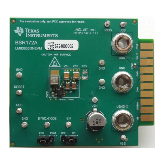
Texas Instruments LM63635DNEVM User Manual (16 pages)
Evaluation Module
Brand: Texas Instruments
|
Category: Control Unit
|
Size: 2 MB
Table of Contents
Advertisement
Texas Instruments LM63635DNEVM User Manual (16 pages)
Brand: Texas Instruments
|
Category: Motherboard
|
Size: 2 MB
Table of Contents

Texas Instruments LM63635DNEVM User Manual (11 pages)
Brand: Texas Instruments
|
Category: Motherboard
|
Size: 1 MB
Table of Contents
Advertisement
Advertisement
Related Products
- Texas Instruments LM63635EVM
- Texas Instruments LM63635DQPWPRQ1
- Texas Instruments LM63635-Q1
- Texas Instruments LM636x5CAQDRRQ1
- Texas Instruments LM63625QDRREVM
- Texas Instruments LM63625EVM
- Texas Instruments LM63625DQPWPTQ1
- Texas Instruments LM63625-Q1
- Texas Instruments LM61460-Q1 EVM
- Texas Instruments LM68645EVM