Sign In
Upload
Manuals
Brands
Texas Instruments Manuals
Motherboard
LM61460EVM
Texas Instruments LM61460EVM Manuals
Manuals and User Guides for Texas Instruments LM61460EVM. We have
1
Texas Instruments LM61460EVM manual available for free PDF download: User Manual
Texas Instruments LM61460EVM User Manual (26 pages)
LM61460-Q1 evaluation module
Brand:
Texas Instruments
| Category:
Motherboard
| Size: 1 MB
Table of Contents
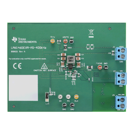
Figure 1-1. LM61460EVM Front
1
Figure 1-2. LM61460EVM Angle
1
Table 1-1. Device and Package Configurations
1
Table of Contents
2
Introduction
4
LM61460 Synchronous Step-Down Voltage Converter
4
Figure 1-1. LM61460-Q1 Pin Configuration (Top View)
4
Figure 1-2. LM61460-Q1
4
LM61460-Q1 Evaluation Module
5
Table 1-1. EVM Variants
5
Quick Start
6
Figure 2-1. Top View of LM61460-Q1 EVM
6
Detailed Descriptions
7
Schematic
9
Figure 4-1. LM61460-AS-400K Rev a EVM Schematic
9
Alternative BOM Configurations
10
Table 4-1. Different BOM Configurations
10
Board Layout
11
Figure 5-1. Top 3D View
11
Figure 5-2. Top Layer
11
Figure 5-3. Signal Layer 1 - Ground Plane
11
Figure 5-4. Signal Layer 2 - Routing
11
Figure 5-5. Bottom Layer
12
Figure 5-6. Bottom 3D View
12
LM61460EVM Board Test Results
13
Emi
13
Figure 6-1. Conducted EMI Measurement with CISPR 25 Class 5 Limit Lines (150 Khz to 30 Mhz)
13
Figure 6-2. Conducted EMI Measurement with CISPR 25 Class 5 Limit Lines (30 Mhz to 110 Mhz)
13
Figure 6-3. Radiated EMI Measurement with Horizontal Bicon Antenna under CISPR 25 Class 5 Limits
13
Figure 6-4. Radiated EMI Measurement with Vertical Bicon Antenna under CISPR 25 Class
13
Board Efficiency
14
Figure 6-5. Radiated EMI Measurement with Horizontal Log Antenna under CISPR 25 Class 5 Limits
14
Figure 6-6. Radiated EMI Measurement with Vertical Log Antenna under CISPR 25 Class
14
Figure 6-7. Radiated EMI Measurement with Rod Antenna under CISPR 25 Class 5 Limits
14
Figure 6-8. FSW = 400 Khz, 5 VOUT, Auto Mode
14
Figure 6-9. FSW = 400 Khz, 5 VOUT, FPWM Mode
14
Figure 6-10. FSW = 400 Khz, 3.3 VOUT, Auto Mode
15
Figure 6-11. FSW = 400 Khz, 3.3 VOUT, FPWM Mode
15
Figure 6-12. FSW = 2.2 Mhz, 5 VOUT, Auto Mode
15
Figure 6-13. FSW = 2.2 Mhz, 5 VOUT, FPWM Mode
15
Figure 6-14. FSW = 2.2 Mhz, 3.3 VOUT, Auto Mode
15
Figure 6-15. FSW = 2.2 Mhz, 3.3 VOUT, FPWM Mode
15
Load Regulation
16
Figure 6-16. FSW = 400 Khz, 5 VOUT, Auto Mode
16
Figure 6-17. FSW = 400 Khz, 5 VOUT, FPWM Mode
16
Figure 6-18. FSW = 400 Khz, 3.3 VOUT, Auto Mode
16
Figure 6-19. FSW = 400 Khz, 3.3 VOUT, FPWM Mode
16
Figure 6-20. FSW = 2.2 Mhz, 5 VOUT, Auto Mode
16
Figure 6-21. FSW = 2.2 Mhz, 5 VOUT, FPWM Mode
16
Figure 6-22. FSW = 2.2 Mhz, 3.3 VOUT, Auto Mode
17
Figure 6-23. FSW = 2.2 Mhz, 3.3 VOUT, FPWM Mode
17
Bill of Materials
18
Table 7-1. LM61460EVM-Xs-400K Rev a EVM Bill of Materials
18
Revision History
20
Advertisement
Advertisement
Related Products
Texas Instruments LM61460-Q1 EVM
Texas Instruments LM636x5CAQDRRQ1
Texas Instruments LM63625QDRREVM
Texas Instruments LM63625EVM
Texas Instruments LM63625DQPWPTQ1
Texas Instruments LM65645EVM
Texas Instruments LM644A2QEVM-S2100T
Texas Instruments LM68645EVM
Texas Instruments LM66200EVM
Texas Instruments LM63635-Q1
Texas Instruments Categories
Motherboard
Control Unit
Microcontrollers
Computer Hardware
Calculator
More Texas Instruments Manuals
Login
Sign In
OR
Sign in with Facebook
Sign in with Google
Upload manual
Upload from disk
Upload from URL