Sign In
Upload
Manuals
Brands
Texas Instruments Manuals
Motherboard
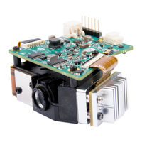
DLP3021LEQ1EVM
Texas Instruments DLP3021LEQ1EVM Board Manuals
Manuals and User Guides for Texas Instruments DLP3021LEQ1EVM Board. We have
1
Texas Instruments DLP3021LEQ1EVM Board manual available for free PDF download: User Manual
Texas Instruments DLP3021LEQ1EVM User Manual (32 pages)
Brand:
Texas Instruments
| Category:
Motherboard
| Size: 1 MB
Table of Contents
Table of Contents
1
DLP3021-Q1 Electronics EVM Overview
3
Introduction
3
What Is in the DLP3021-Q1 Light Engine EVM
3
Figure 1-1. DLP3021LEQ1EVM Block Diagram
4
Figure 1-2. DLP3021LEQ1EVM Unit
4
Figure 1-3. Operating Mode Switches: Electronics Board S1-A and S1-B Switches
5
Figure 1-4. Operating Mode Switches: SPI Adapter Board S1 and S2 Switches
5
Table 1-1. DLP3021LEQ1 EVM Operating Mode Switch Positions
6
Table 1-2. Light Engine Performance Specifications
7
Table 1-3. DLP3021LEQ1EVM Cables
7
Non-Optical Specifications
8
Figure 1-5. Cables Included in DLP3021LEQ1EVM for FTDI
8
Table 1-4. Electrical Specifications
8
Figure 1-6. LED Driver Timing Specifications
9
Table 1-5. LED Driver Timing Specifications
9
Quick Start
10
Kit Assembly Instructions
10
Figure 2-1. Cable Connections
10
Figure 2-2. Assembled DLP3021-Q1 Light Engine EVM with FTDI
10
Table 2-1. FTDI C232HM MPSSE Cable to SPI Adapter Board Connections
10
Software Installation
11
Power-Up
11
Select Display Content
11
Figure 2-3. Host Mute Operating Mode LED Status
11
LED Driver
12
Figure 2-4. Successful FTDI Cable Connection Established in GUI
12
Table 2-2. LED PWM Drive Current Conversion Reference
13
Optics and Mechanics
14
Software
15
DLP Composer
15
Figure 4-1. DLP Composer - Default Register Configuration
15
Figure 4-2. DLP Composer - Illumination
16
Figure 4-3. DLP Composer - Sequence Set
16
Figure 4-4. DLP Composer - Degamma Curves
17
Figure 4-5. DLP Composer - Image/Video
18
Figure 4-6. DLP Composer - Flash Blocks
19
Table 4-1. Top Level Flash Structure
19
Table 4-2. Flash Information Block
20
Figure 4-7. DLP Composer - Flash Programming
21
Figure 4-8. Flash Programming Operating Mode LED Status
21
DLP Control Program
22
Figure 4-9. DLP Composer - Connections
22
Figure 4-10. DLP Control Program - Connection
23
Figure 4-11. DLP Control Program - Scripting
23
Figure 4-12. DLP Control Program - Scripting Reference
24
Figure 4-13. DLP Control Program - Registers
24
MSP430 Example Code
25
Figure 4-14. DLP Composer - Commands
25
Revision History
26
Evm
26
Advertisement
Advertisement
Related Products
Texas Instruments DLP3010
Texas Instruments DLP3010EVM-LC
Texas Instruments DLP3030-Q1
Texas Instruments DLP3030CHUDQ1EVM
Texas Instruments DLP5530PGUQ1EVM
Texas Instruments DLP5530PROJQ1EVM
Texas Instruments DLP5532HBQ1EVM
Texas Instruments DLP4710EVM-LC
Texas Instruments DLPC4430
Texas Instruments DLPA2005
Texas Instruments Categories
Motherboard
Control Unit
Microcontrollers
Computer Hardware
Calculator
More Texas Instruments Manuals
Login
Sign In
OR
Sign in with Facebook
Sign in with Google
Upload manual
Upload from disk
Upload from URL