Sign In
Upload
Manuals
Brands
Texas Instruments Manuals
Motherboard
AM62x SK EVM
Texas Instruments AM62x SK EVM Manuals
Manuals and User Guides for Texas Instruments AM62x SK EVM. We have
1
Texas Instruments AM62x SK EVM manual available for free PDF download: User Manual
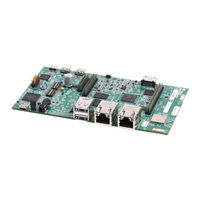
Texas Instruments AM62x SK EVM User Manual (69 pages)
Brand:
Texas Instruments
| Category:
Motherboard
| Size: 10 MB
Table of Contents
Table of Contents
1
EVM Revisions and Assembly Variants
4
Table 1-1. SK EVM PCB Design Revisions, and Asssembly
4
System Description
5
Figure 2-1. SK-AM62 Top View
5
Key Features
6
Figure 2-2. SK-AM62 Back View
6
Functional Block Diagram (SK-AM62)
8
Functional Block Diagram (SK-AM62-P1)
9
Figure 2-3. Functional Block Diagram of the Am62X SKEVM Board
9
Figure 2-4. Functional Block Diagram of the Am62X SKEVM Board with TPS65219 PMIC
10
Am62X SKEVM Interface Mapping
11
Power ON/OFF Procedures
11
Table 2-1. Interface Mapping
11
Figure 2-5. SD Bootmode Switch Setting Example (E2, E3)
12
Peripheral and Major Component Description
13
Figure 2-6. SD Bootmode Switch Setting Example (E1)
13
Table 2-2. Power Test Points
13
Figure 2-7. Clock Architecture of Am62X SKEVM
14
Figure 2-8. Soc WKUP Domain
14
Table 2-3. Clock Table
15
Table 2-4. Display Connector Pinout
16
Table 2-5. Display Connector Pinout (E1/E2)
17
Table 2-6. CSI Camera Connector J19 Pin-Out
18
Table 2-7. JTAG Connector (J17) Pin-Out
21
Table 2-8. Test Automation Connector (J23) Pin-Out
23
Table 2-9. UART Port Interface
24
Table 2-10. IO Expander Signal Detail
36
Table 2-11. GPIO Mapping
38
Table 2-12. Type-C Port Power Roles
40
Table 2-13. Recommended External Power Supply
40
Table 2-14. Soc Power Supply
48
Table 2-15. INA I2C Device Address (E1)
48
Table 2-16. INA I2C Device Address (E2)
49
Figure 2-9. Bootmode Switch Configuration for SD Boot (E2, E3)
50
Figure 2-10. Bootmode Switch Configuration for SD Boot (E1)
51
Table 2-17. BOOT-MODE Pin Mapping
51
Table 2-18. PLL Reference Clock Selection BOOTMODE [2:0]
51
Table 2-19. Boot Device Selection BOOT-MODE [6:3]
52
Table 2-20. Backup Boot Mode Selection BOOT-MODE [12:10]
52
Table 2-21. Primary Boot Media Configuration BOOT-MODE [9:7]
52
Table 2-22. Backup Boot Media Configuration BOOT-MODE
53
Table 2-23. User Test Leds
53
Table 2-24. PRU Header (J10) Pin-Out
54
Table 2-25. 40 Pin User Expansion Connector
55
Table 2-26. Pin MCU Connector (J9)
57
Table 2-27. EVM Push Buttons
59
Table 2-28. I2C Mapping Table (SK-AM62 E3 and SK-AM62-P1 Variants)
60
Table 2-29. I2C Mapping Table (SK-AM62 E2)
63
Known Issues and Modifications
64
Issue 1 - HDMI/DSS Incorrect Colors on E1
64
Issue 2 - J9 and J10 Header Alignment on E1
64
Table 3-1. Am62X SK EVM Known Issues and
64
Issue 3 - USB Boot Descoped on E1
65
Issue 4 - OLDI Connector Orientation and Pinout
65
Issue 5 - Bluetooth Descoped on E2 Evms
65
Issue 6 - Ethernet PHY CLK Skew Default Strapping Changes
65
Figure 3-1. PRU Connector Missalignment on E1 Boards
65
Issue 7 - TEST_POWERDOWN
66
Changes
66
Issue 8 - MMC1_SDCD Spurious Interrupts
66
Issue 9 - PD Controller I2C2 IRQ Not Pinned out
66
Issue 10 - INA Current Monitor Adress Changes
66
Issue 11 - Test Automation I2C Buffer Changes
66
Figure 3-2. Schematic of I2C Buffer Section
67
Figure 3-3. Location on Am62X SK E3 (Bottom Side)
67
Regulatory Compliance
68
Revision History
68
Modifications
68
Advertisement
Advertisement
Related Products
Texas Instruments AM62-SIP SK Series
Texas Instruments AM625
Texas Instruments AM623
Texas Instruments AM625SIP
Texas Instruments AM625-Q1
Texas Instruments AM620-Q1
Texas Instruments AM62L
Texas Instruments AM64 GP EVM Series
Texas Instruments AM64x
Texas Instruments AM654 Series
Texas Instruments Categories
Motherboard
Control Unit
Microcontrollers
Computer Hardware
Calculator
More Texas Instruments Manuals
Login
Sign In
OR
Sign in with Facebook
Sign in with Google
Upload manual
Upload from disk
Upload from URL