Sign In
Upload
Manuals
Brands
Texas Instruments Manuals
Motherboard
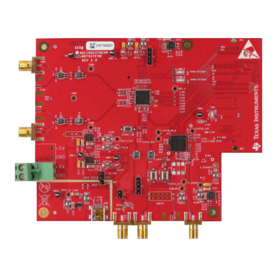
ADC16DX370EVM
Texas Instruments ADC16DX370EVM Manuals
Manuals and User Guides for Texas Instruments ADC16DX370EVM. We have
1
Texas Instruments ADC16DX370EVM manual available for free PDF download: User Manual
Texas Instruments ADC16DX370EVM User Manual (25 pages)
Brand:
Texas Instruments
| Category:
Motherboard
| Size: 1 MB
Table of Contents
Table of Contents
2
Introduction
4
Equipment
6
Evaluation Board Feature Identification Summary
6
Required Equipment
6
EVM Feature Locations
6
Setup Procedure
7
Install the High Speed Data Converter Pro (HSDP) Software
7
Install the Configuration GUI Software
7
Connect the EVM and TSW14J56EVM
7
EVM Test Setup
7
Connect the Power Supplies to the Boards (Power Off)
8
Connect the Signal Generators to the EVM (RF Signal Off)
8
Turn the TSW14J56EVM Power on and Connect to the PC
8
Turn the EVM Power Supplies on and Connect to the PC
8
Turn the Signal Generator RF Outputs on
8
Open the HSDP Software and Load the FPGA Image to the TSW14J56EVM
8
3.10 Program the LMK04828 Using the Configuration Tab on the HSDC Pro Software
9
3.11 Calibrate the ADC Device on the EVM
9
Verify the TSW14J56EVM Switch Settings, Initialize the JESD204B Link (CPU_RESET), and Verify TSW14J56EVM Status Leds
9
Default State of Leds on the TSW14J56EVM During Typical Operation
9
3.13 Capture Data Using the HSDP Software
10
3.14 Re-Verify TSW14J56EVM Status Leds
11
High Speed Data Converter Pro (HSDP) GUI
11
Default State of Leds on the TSW14J56EVM During Typical Operation
11
Device Configuration
12
Supported JESD204B Device Features
12
Using the Device Configuration GUI
12
Configuration GUI Intro Tab
13
Configuration GUI ADC Core Tab
13
Tab Organization
14
Low-Level Control
14
Low-Level Controls
14
Low-Level Register Control Tab
15
Evaluation Troubleshooting
16
References
16
TSW14J56EVM LED Bank and Switch Configuration
17
Meaning of Leds on the TSW14J56EVM
17
HSDC Pro Settings for Optional ADC Device Configuration
18
Changing the Number of Serial Output Lanes (L)
18
Changing the Number of Frames Per Multi-Frame (K)
18
Exercising the SYSREF Input of the ADC
18
Customizing the EVM for Optional Clocking Support
18
LMK04828 Configuration Options
18
Configuring the ADC Device to Use a Device Clock and SYSREF from the LMK04828
19
Providing an Alternate LMK04828 Reference Clock
19
Revision History
19
Advertisement
Advertisement
Related Products
Texas Instruments ADC161S626BEB
Texas Instruments ADC161S626
Texas Instruments ADC1xD1x00CVAL Series
Texas Instruments ADC1 D (RF )RB Series
Texas Instruments ADC12D800RF
Texas Instruments ADC12D1600RF
Texas Instruments ADC10D1500
Texas Instruments ADC12DJ3200EVM
Texas Instruments ADC12DJ2700
Texas Instruments ADC12DL3200
Texas Instruments Categories
Motherboard
Control Unit
Microcontrollers
Computer Hardware
Calculator
More Texas Instruments Manuals
Login
Sign In
OR
Sign in with Facebook
Sign in with Google
Upload manual
Upload from disk
Upload from URL