Sign In
Upload
Manuals
Brands
Terrasat Manuals
Media Converter
IBUC 3
Terrasat IBUC 3 Manuals
Manuals and User Guides for Terrasat IBUC 3. We have
1
Terrasat IBUC 3 manual available for free PDF download: Operation Manual
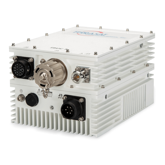
Terrasat IBUC 3 Operation Manual (236 pages)
Intelligent Block Upconverter
Brand:
Terrasat
| Category:
Media Converter
| Size: 20 MB
Table of Contents
Table of Contents
3
Preface
15
Conventions and References
15
Table P.1 Typographical Conventions
15
Cautions and Warnings
16
Electrical Safety Notice
16
Trademarks
16
Chapter 1, Introduction
17
Block Upconverters
17
Reference Documents
18
Table 1.1 Satellite Operation Standards
18
Warranty Information
21
Chapter 2, Functional Description
23
Introduction
23
System Components
24
Table 2.1 IBUC 3 Transmit Frequency Plans
25
Table 2.2 IBUC 3G Transmit Frequency Plans
26
DC Supply
27
Monitor and Control
29
RF Signal Flow
29
Figure 2.2 DC-Powered Low-Power IBUC3 Block Diagram
32
Figure 2.3 DC-Powered IBUC3 Block Diagram
33
Software
34
System Configurations
35
Table 2.5 Basic System Requirements
35
Figure 2.4 DC Low Power IBUC System Configuration
37
Figure 2.5 DC Power IBUC System Configuration
38
Storage Information
39
Chapter 3, Installation
41
Introduction
41
General Requirements
41
Unpacking
41
Furnished Items
42
Figure 3.1 Furnished Items with IBUC
42
Accessories
43
Installing the ODU
43
Test Equipment
43
Site Considerations
43
Table 3.1 Recommended Test Equipment
43
Mounting Considerations
44
Power Requirements
44
Grounding
45
Table 3.2 Terrasat Outdoor Power Supplies
45
Antenna Recommendations
46
Antenna Mounting
47
Figure 3.2 IBUC 3 Field Installation
47
Figure 3.3 Location of Mounting Holes
48
Figure 3.4 IBUC in Line Mounting Configuration
48
System Pressurization
49
Figure 3.5 Location of Adjustment Slots on Optional Mounting Bracket
49
System Cabling Requirements
50
Table 3.4 Pin Assignments for M&C Interface Connector J2
51
Figure 3.6 Connector J1 Caution Symbol
51
Table 3.5 Pin Assignments for DC Power Connector J3
52
Cable and Waveguide Connections
53
Figure 3.7 Applying the Anti-Seize Lubricant
55
Basic System Alignment
56
Figure 3.8 Waveguide Label and Channel for Gasket
56
Setting the Tx and Rx Frequencies
57
Transmit Power Alignment
58
Transmit RF Output Adjustment with Modem or Converter (70 Mhz to L-Band)
58
Final Checks
59
Chapter 4, Operations
61
Introduction
61
Start-Up Checklist
61
Turning on the IBUC
62
Setting Operating Parameters
62
Setting the Tx Frequency (L-Band)
64
Setting Alarm Thresholds
64
Configuring Alarm States
65
Configuring ALC/AGC
65
Configuring the External Mute
66
Common Errors
67
LED Is Red
67
No Power to the IBUC 3 or IBUC 3G
67
Time Stamp Data Is Incorrect
68
Satellite Network Operations Center Doesn't Recognize Signal
68
Transmit Power in Saturation
69
Tx Input/Output Level Verification
69
Chapter 5, Monitor and Control Features
71
Introduction
71
M&C Interfaces
71
Rs232
71
Hand-Held Terminal
71
Figure 5.1 Hand-Held Terminal
72
Multifunction LED
73
Table 5.1 Default Alarm Configuration
73
Frequency Shift Keying (FSK) Modem Interface
74
Rs485
75
Table 5.2 Transmitter Link Specifications
75
Table 5.3 Receiver Link Specifications
75
ASCII Mode
76
Table 5.4 ASCI Mode Command Format
76
Legacy Binary Mode
77
Table 5.5 Legacy Binary Mode Packet Format
77
Table 5.6 Data Packet Byte Configuration
77
Ethernet
78
Determining the IP Address of Your IBUC
78
Telnet
78
Web Server
79
Snmp
79
Power Measurement
80
Input Power Overdrive Protection
81
Chapter 6, Troubleshooting
83
Maintenance
83
Transceiver Fault Isolation
83
Site-Related Problems
83
M&C Checks
83
Power Supply Checks
84
Transmit Power Setting
84
Common Problems
85
Tx Output Is Disabled
85
Incorrect Frequency Settings
85
Damaged Cables
86
10 Mhz Reference Signal Is at the Wrong Level or Missing
86
Table 6.1 Possible Scenarios for Ibucs with an External 10 Mhz Reference Signal
86
Antenna Is Pointed Toward Wrong Satellite or Is Misaligned
87
Moisture Migrated into the IBUC
87
Bad Orthogonal Mode Transducer And/Or Antenna
88
LED Is Red
88
Repair Policy
88
Returned Material Authorization (RMA)
89
Chapter 7, Transmit Redundant Systems
91
Description
91
Figure 7.1 Transmit Redundant System Setup
91
Interface for Tx Redundant (1+1) Systems
92
Figure 7.2 IBUC 3 Redundant System Diagram
93
Component Description
94
Intelligent Block Upconverter
94
Tx 1+1 Interface Module
94
Waveguide Switch
95
Software
95
Installation and Setup
96
System Cabling Requirements
97
Tx 1+1 System
97
Tx 1+1 Interface Module
97
Figure 7.4 Tx 1+1 Interface Module View
97
Table 7.2 Pin Assignments for M&C Interface Connectors J1, J2, and J3
99
Table 7.3 Pin Assignments for M&C Interface Connectors J4 and J6
99
Table 7.4 Pin Assignments for M&C Interface Connectors J5, J7, J8, and J10
100
Table 7.5 Pin Assignments for M&C Interface Connector J9
100
Cable and Waveguide Connections
101
Table 7.6 Pin Assignment for M&C Interface Connector J11
101
Typical Initial Setup
102
Water-Resistant Wrap
102
Grounding
103
Antenna Recommendations
103
Tx Redundancy/Psui Grounding Recommendations
104
System Alignment and Operation
104
General
104
Test Equipment
105
Setting the Tx Frequencies
105
Tx Power Alignment
105
Table 7.7 Recommended Test Equipment
105
Final Checks
106
M&C Setup
107
Tx Redundant System
107
General
107
Figure 7.5 Multifunction Leds for a Tx 1+1 System
112
Service and Maintenance
113
Standard Maintenance
113
Fault Isolation
113
M&C Functions
118
User Interfaces
118
RS485 in ASCII Mode
119
Figure 7.6 Hand-Held Terminal
119
TCP/IP Via Ethernet Cable
120
Repair Policy
120
Appendix A, Part Numbering Schema
121
Identifying the Part and Serial Numbers
121
Decoding the Part Number
121
Appendix B, Using Hyperterminal
125
Establishing a Hyperterminal Session
125
Using a Saved Connection
130
Ending a Hyperterminal Session
131
Appendix C, Embedded Web Pages
133
Introduction
133
Screen Shots
136
Log in
136
Information Tab
136
Alarm Tab
138
Sensor Tab
141
Transmit Configuration Tab
142
Table C.1 Default Values for Power Monitor Frequency
143
Table C.2 Default Values for the Burst Threshold
144
Interface Configuration Tab
145
System Configuration Tab
148
Alarm Configuration Tab
150
Redundancy Configuration Tab
152
Event Log Tab
154
Appendix D, Hand-Held Terminal Menu Tree
155
Menu Options
155
Info & Sensors
158
Alarm
159
Tx Thresholds
159
Interface
159
Snmp
160
System
160
Redundancy
161
Appendix E, Legacy Binary Command Message Structure
163
Command Set
163
Table E.1 Commands
163
Table E.3 Response to IBUC Commands 0X05 and 0X06
165
Table E.4 Response to IBUC Command 0X06 (When Data Byte 1 of Command Message = 0X01
166
Table E.5 Response to IBUC Command 0X07
166
Table E.6 Response to IBUC Command 0X09
166
Legacy Response Message Structure
167
Data Field Definitions
167
Table E.7 Data Filed Definitions
167
Appendix F, ASCII Command/Response Structure Command Set
169
Table F.1 Alarm Mask
169
Table F.2 Alarm Flags
170
Table F.3 Error Response Table
170
Common Commands
172
Transmit-Only Commands
192
Table F.4 Default Values for the TAH, TAL, and TBT Commands
201
Table F.5 Band Numbering
203
Table F.6 Default Values for the TFR Command
205
Redundancy Commands
212
Appendix G, Component Specifications and Reference Drawings
221
Reference Drawings
221
Figure G.1 Fabrication Drawing, FBD-21012-XXXX, Rev a
222
Data Sheets
226
Appendix D, Glossary
229
Glossary of Terms
229
Advertisement
Advertisement
Related Products
Terrasat IBUC 2
Terrasat IBUC R
Terrasat IBUC
Terrasat IBUC G
Terrasat IBUC 2e
Terrasat IBUC 2G
Terrasat IBUC 2s
Terrasat IBUC 3G
Terrasat Categories
Media Converter
Recording Equipment
More Terrasat Manuals
Login
Sign In
OR
Sign in with Facebook
Sign in with Google
Upload manual
Upload from disk
Upload from URL