Teridian 71M6513 Manuals
Manuals and User Guides for Teridian 71M6513. We have 2 Teridian 71M6513 manuals available for free PDF download: User Manual

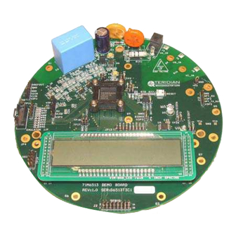
Teridian 71M6513 User Manual (113 pages)
Brand: Teridian
|
Category: Control Unit
|
Size: 2 MB
Table of Contents
Advertisement
Teridian 71M6513 User Manual (113 pages)
Brand: Teridian
|
Category: Motherboard
|
Size: 2 MB