Sign In
Upload
Manuals
Brands
Terex Manuals
Scissor Lifts
Genie GS-3268 RT
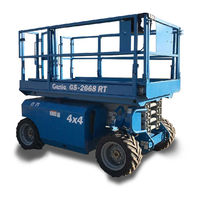
Terex Genie GS-3268 RT Manuals
Manuals and User Guides for Terex Genie GS-3268 RT. We have
2
Terex Genie GS-3268 RT manuals available for free PDF download: Service Manual, Operator's Manual
Terex Genie GS-3268 RT Service Manual (184 pages)
Brand:
Terex
| Category:
Lifting Systems
| Size: 3 MB
Table of Contents
Introduction
2
Serial Number Information
2
Serial Number Legend
3
Safety Rules
5
Personal Safety
6
Workplace Safety
6
Table of Contents
7
Machine Specifications
15
Performance Specifications
16
Hydraulic Specifications
16
Hydraulic Components Specifications
17
Manifold Component Specifications
18
Valve Coil Resistance Specifications
18
Kubota D1105 Engine Tier 4
19
Kubota D905 Engine Tier 2
20
Kubota DF752 Engine
21
Perkins 403D-11 Engine
22
Perkins 403C-11 Engine
23
Hydraulic Hose and Fitting Torque Specifications
24
Sae Fastener Torque Chart
25
Metric Fastener Torque Chart
25
Scheduled Maintenance Procedures
27
Observe and Obey
27
About this Section
27
Pre-Delivery Preparation Report
28
Maintenance Inspection Report
31
Checklist a Procedures
33
Inspect the Manuals and Decals
33
Perform Pre-Operation Inspection
34
Perform Function Tests
34
Perform Engine Maintenance
35
Inspect the Engine Air Filter
35
Perform 30 Day Service
36
Perform Engine Maintenance - Kubota Models
37
Perform Engine Maintenance - Kubota Models
38
Drain the Fuel Filter/Water Separator - Diesel Models
39
Perform Engine Maintenance - Kubota Models
40
Checklist B Procedures
41
Inspect the Battery
41
Electrocution/Burn Hazard
41
Inspect the Electrical Wiring
42
Inspect the Tires, Wheels and Lug Bolt Torque
43
Perform Engine Maintenance - Perkins Models
43
Test the Key Switch
44
Test the Emergency Stop
44
Test the Automotive-Style Horn
45
Test the Fuel Select Operation - Gasoline/Lpg Models
45
Test the Drive Brakes
46
Test the Drive Speed - Stowed Position
47
Test the Drive Speed - Raised Position
48
Inspect the Fuel and Hydraulic Tank Cap Venting Systems
48
Perform Hydraulic Oil Analysis
49
Test the Flashing Beacons (if Equipped)
50
Perform Engine Maintenance - Kubota Models
50
Checklist C Procedures
51
Test the Platform Overload System (if Equipped)
51
Clean the Fuel Tank - Diesel Models
52
Replace the Hydraulic Tank Breather Cap - Models with Optional Hydraulic Oil
53
Perform Engine Maintenance - Diesel Models
53
Perform Engine Maintenance - Kubota Models
54
Checklist D Procedures
55
Check the Scissor Arm Wear Pads
55
Replace the Hydraulic Tank Return Filter
56
Or Spray
56
Perform Engine Maintenance - Perkins Models
57
Perform Engine Maintenance - Kubota Models
57
Perform Engine Maintenance - Kubota Models
58
Checklist E Procedures
59
Test or Replace the Hydraulic Oil
59
Perform Engine Maintenance - Perkins Models
60
Perform Engine Maintenance - Gasoline/Lpg Models
61
Perform Engine Maintenance - Kubota D1105 Models
61
Perform Engine Maintenance - Perkins Models
62
Perform Engine Maintenance - Kubota D1105 Models
62
Repair Procedures
63
About this Section
63
Observe and Obey
63
Platform Controls
64
Circuit Boards
64
Platform Components
65
Platform
65
Platform Extension
66
Scissor Components
68
Scissor Assembly, GS-2668 RT
69
Scissor Assembly, GS-3268 RT
75
Wear Pads
81
Lift Cylinder(S)
82
Kubota D1105 and D905 Engines
85
Timing Adjustment
85
Glow Plugs
85
Engine RPM
86
Flex Plate
86
How to Install the Flex Plate
87
Coolant Temperature and Oil Pressure Switches
87
Kubota DF752 Engine
89
Timing Adjustment
89
Carburetor Adjustment - Gasoline/Lpg Models
89
Choke Adjustment - Gasoline/Lpg Models
89
Flex Plate
89
Coolant Temperature and Oil Pressure Switches
89
Engine RPM
90
Timing Adjustment
91
Flex Plate
92
Coolant Temperature and Oil Pressure Switches
92
Ground Controls
94
Auxiliary Platform Lowering
94
Function Speed Tuning
94
How to Determine the Revision Level
94
How to Adjust the Stowed Drive Speed
95
How to Adjust the High Torque Drive Speed
96
How to Adjust the Raised Drive Speed
97
How to Adjust the Lift Speed
98
Software Configuration
99
Level Sensor - Models Without Outriggers
105
Level Sensor - Models with Outriggers
108
Hydraulic Pump
112
How to Remove the Hydraulic Pump
113
How to Prime the Pump
113
Function Manifold Components
114
Valve Adjustments - Function Manifold
118
How to Adjust the Steer Relief Valve
119
Outrigger Manifold Components
121
Valve Adjustments - Outrigger Manifold
122
Generator Manifold Components
124
Valve Adjustments - Generator Manifold
125
Valve Coils
126
Fuel and Hydraulic Tanks
128
Fuel Tank
128
Hydraulic Tank
129
Steer Axle Components
130
Yoke and Drive Motor
130
Connections very Slowly to Allow
130
How to Remove a Drive Motor
131
Gradually. Do Not Allow Oil to Squirt
131
Steer Cylinder
132
Tie Rod
132
Non-Steer Axle Components
133
Drive Motor and Brake
133
Outrigger Components
134
Outrigger Cylinder
134
Brake Release Hand Pump Components
135
Platform Overload Components
136
Platform Overload System
136
Hydraulic Oil Can Penetrate and Burn Skin. Loosen Hydraulic
143
Observe and Obey
143
Troubleshooting and Repair Procedures Shall be Completed by a Person Trained and Qualified on the Repair of this Machine
143
Immediately Tag and Remove from Service a Damaged or Malfunctioning Machine
143
Repair any Machine Damage or Malfunction before Operating the Machine
143
Fault Codes
143
Before Troubleshooting
143
Read, Understand and Obey the Safety Rules and Operating Instructions in the Appropriate Operator's Manual on Your Machine
143
Be Sure that All Necessary Tools and Test Equipment Are Available and Ready for Use
143
Bodily Injury Hazard. Spraying
143
About this Section
144
General Repair Process
144
Identify Troubleshoot
144
Malfunction Discovered
144
Problem Still Exists
144
Return to
144
Fault Code Chart (from Serial Number GS6805-44771)
145
Electronic Control Module Layout (from Serial Number GS6805-44771)
150
Section 6 • Schematics
150
Electronic Control Module Pin-Out Legend (from Serial Number GS6805-44771)
151
Wiring Diagram - Platform Control Box (from Serial Number GS6805-44771)
152
Electrical Schematics Abbreviation and Wire Color Legends
154
Electrical Symbols Legend
155
C Electrical Schematic - ANSI Models with Gasoline/Lpg Power
156
(From Serial Number GS6805-44771)
156
(From Serial Number GS6805-44771)
157
C Electrical Schematic - ANSI Models with Diesel Power
164
(From Serial Number GS6805-44771 to GS6806-45204)
164
(From Serial Number GS6806-45205)
168
C Electrical Schematic - CE Models with Diesel Power
172
(From Serial Number GS6805-44771 to GS6806-45204)
172
(From Serial Number GS6806-45205)
176
Hydraulic Symbols Legend
179
Hydraulic Schematic (from Serial Number GS6805-44771)
180
Advertisement
Terex Genie GS-3268 RT Operator's Manual (46 pages)
Brand:
Terex
| Category:
Scissor Lifts
| Size: 1 MB
Table of Contents
Table of Contents
2
Introduction
3
Symbols and Hazard Pictorials Definitions
5
General Safety
7
Personal Safety
9
Work Area Safety
10
Legend
17
Controls
18
Inspections
24
Operating Instructions
32
Transport and Lifting Instructions
38
Maintenance
41
Specifications
44
Advertisement
Related Products
Terex Genie GS-3268DC
Terex Genie GS-3232
Terex Genie GS-3246
Terex Genie GS-3246 XH
Terex GS3212C-10000
Terex GS3216C-17299
Terex GS3216P-142676
Terex GS32C-17300
Terex GS32D-10100
Terex GS32P-148700
Terex Categories
Boom Lifts
Lifting Systems
Construction Equipment
Scissor Lifts
Compact Loader
More Terex Manuals
Login
Sign In
OR
Sign in with Facebook
Sign in with Google
Upload manual
Upload from disk
Upload from URL