Sign In
Upload
Manuals
Brands
Telit Wireless Solutions Manuals
Control Unit
G30
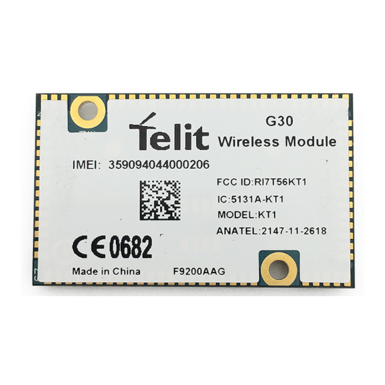
Telit Wireless Solutions G30 Manuals
Manuals and User Guides for Telit Wireless Solutions G30. We have
1
Telit Wireless Solutions G30 manual available for free PDF download: Hardware User's Manual
Telit Wireless Solutions G30 Hardware User's Manual (104 pages)
GSM/GPRS Surface Mount, LGA Module
Brand:
Telit Wireless Solutions
| Category:
Control Unit
| Size: 1 MB
Table of Contents
VV0300919 Rev.0 – 2011
4
Table of Contents
5
1 Introduction
12
Scope
12
Audience
12
Contact Information, Support
12
Required Query Information
13
Testing a Standalone Unit
14
Test Setup
14
Test Procedure
15
Figure 1-1: Test Setup
15
Document Organization
16
Text Conventions
16
Related Documents
16
Regulatory Requirements
16
Regulatory Statement (Safety)
17
FCC Notice to Users
17
Precautions
18
Antenna and Transmission Safety Precautions
18
User Operation
18
Antenna Installation
18
Section 15.203 - Antenna Requirements
19
Standards
19
General Safety
20
Remember
20
Ground the Instrument
20
Do Not Operate in an Explosive Atmosphere
20
Do Not Service or Adjust Alone
20
Keep Away from Live Circuits
21
Do Not Substitute Parts or Modify Equipment
21
Dangerous Procedure Warnings
21
Caring for the Environment
21
Disposal of Telit Equipment in EU Countries
21
Disposal of Telit Equipment in Non-EU Countries
21
Turkey
22
2 General Product Description
23
Product Specifications
23
Regulatory and Approvals
27
Table 2-1: G30 Product Specifications
27
CFR 47 Part 15.105 Information to the User
28
CFR 47 Part 15.19 Specifies Label Requirements
28
CFR 47 Part 15.21 Information to User
28
European Union Directives Conformance Statement
28
3 Hardware Interface Description
30
Architecture Overview
30
Figure 3-1: G30 Block Diagram
30
Baseband
31
RF Block
31
Operating Modes
31
Table 3-1: G30 Operating Modes
32
Power Supply
33
Power Supply Design
33
Table 3-2: Power Supply Signals
33
Figure 3-2: Transmission Power Drops
33
Power Consumption
34
Table 3-3: Recommended Power Supply Filtering
34
Power On/Off Operation
35
Turning the G30 on
35
Table 3-4: G30 Current Ratings
35
Power Supply Turn-On
36
Turning the G30 on Using PWR_ON
36
Turning the G30 off
36
Figure 3-3: Power Supply Turn-On
36
Figure 3-4: PWR_ON Power on Timing
36
Turning the G30 off Using PWR_ON
37
Power Loss Shut down
37
Turning the G30 off Using AT+MRST
37
Low Power Mode
37
Activating Low Power Mode
37
Figure 3-5: PWR_ON Power off Timing
37
Serial Interface During Low Power Mode
38
Figure 3-6: ATS24 Operation
38
Figure 3-7: CTS Signal During Sleep Mode
38
Terminating Low Power Mode
39
Figure 3-8: WKUPI Signal Operation
39
Figure 3-9: Serial Interface Data
40
Real Time Clock
41
Serial Interfaces
41
Uart
41
Figure 3-10: UART Interface Signals
42
Figure 3-11: RI Behaviour When Receiving a Call
42
Serial Peripheral Interface (SPI)
43
Flashing and Data Logging
44
Table 3-5: SPI Interface Connections
44
I 2 C Bus Interface
46
Table 3-6: Data Logging and SW Upgrading Application Connector
46
SIM Interface
47
Table 3-7: I2C Interface Connections
47
1VV0300919 Rev.0 - 2011-05-04
48
External SIM Card
48
Figure 3-12: G30 External SIM Interface
48
Table 3-8: SIM Interface Signals
48
Embedded SIM
49
Esim Connection
49
Figure 3-13: G30 Esim Interface
49
Audio Interface
50
Handset Microphone Port
50
Figure 3-14: Audio Interface Topology
50
Headset Microphone Port
51
Table 3-9: Handset Microphone Port Specifications
51
Figure 3-15: Handset Microphone Circuit
51
Table 3-10: Headset Microphone Port Specifications
52
Figure 3-16: Headset Microphone Circuit
52
Differential Speaker (Handset) Port
53
Figure 3-17: Differential Speaker Circuit
53
Figure 3-18: Single-Ended Speaker Circuit
53
Mono Speaker (Headset) Port
54
Table 3-11: Speaker Port Specifications
54
Figure 3-19: Mono Speaker (Headset) Circuit
54
Headset Detection
55
Table 3-12: Mono Speaker Port Specifications
55
Digital Audio Interface
56
Voiceband Audio
56
Table 3-13: Digital Audio Modes
56
Operating Modes
57
Figure 3-20: I2S BUS Format
57
Figure 3-21: Voiceband Mode PCM Bus Coding Format
57
Table 3-14: Basic Mode Audio Paths
58
Audio Programming Interface
59
Table 3-15: Advanced Mode Commands
59
Figure 3-22: Audio Programming Interface
59
Audio Design
60
Table 3-16: Speech Processing Features
60
Table 3-17: Gain Control Features
60
A/D Interface
61
Power Supply A/D
62
General Purpose A/D
62
Table 3-18: Supply A/D Specifications
62
Controls and Indicators Interface
63
Table 3-19: GPAD Specifications
63
Reset
65
Table 3-20: Controls and Indicators
65
VREF Reference Regulator
65
Table 3-21: VREF Specifications
66
Vrtc
66
Wakeup out
66
Antenna Detection
67
Figure 3-23: WKUPO Operation
67
General Purpose I/O
68
GPRS Detection
68
Antenna Interface
68
Specifications
69
Table 3-22: Antenna Interface Specifications
70
4 Electrical and Environmental Specifications
71
Absolute Maximum Ratings
71
Table 4-1: Maximum Ratings
71
Operating Parameters
72
Supply/Power Pins
72
Table 4-2: Input Characteristics
72
Table 4-3: Output Characteristics
72
Digital Pins
73
Table 4-4: Input Characteristics
73
Table 4-5: Output Characteristics
75
Table 4-6: Pad Pull-Up and Pull-Down Characteristics
76
Audio Pins
77
Table 4-7: Audio Transmit Path Characteristics
78
Table 4-8: Microphone Supply Characteristics
78
Table 4-9: G30 Low Power Single-Ended Audio Receive Path Characteristics
79
ADC Pins
80
Table 4-10: G30 High Power Differential Audio Receive Path Characteristics
80
Environmental Specifications
81
Table 4-11: Input Characteristics
81
Application Interface Specifications
82
Table 4-12: Environmental Ratings
82
Figure 4-1: G30 - 70 Pin Connector Quick Integration Connections
83
Figure 4-2: G30 - 81 Pin LGA Interface Quick Integration Connections
84
Table 4-13: Interface Specifications
91
5 Mechanical Specifications
92
Board Dimensions
92
Figure 5-1: G30 Mechanical Characteristics - 81 Pin LGA Interface
92
Figure 5-2: G30 Mechanical Characteristics - B2B Connector (70 Pin)
93
LGA Tape & Reel Specification
94
Figure 5-3: LGA Tape & Reel Specification
94
Interface Connector Specifications
95
Table 5-1: Interface Connector Specifications
95
Mating Connector
96
U.FL Connector Specifications
96
Figure 5-4: Mating Connector Dimensions
96
Figure 5-5: U.FL Connector Dimensions
97
Mating Connector
98
G30 Mounting
98
Table 5-2: U.FL Connector Specifications
98
Figure 5-6: U.FL Mating Connector
98
Layout Recommendation
99
Figure 5-7: G30 Mounting Area
99
Figure 5-8: G30 Soldering Footprint (Top View)
100
RF Recommendation
100
Soldering Footprint
100
Soldering Re-Flow
101
Table 5-3: Soldering Re-Flow Process
101
Figure 5-9: Soldering Re-Flow Process
101
6 Acronyms and Abbreviations
103
Document History
104
Advertisement
Advertisement
Related Products
Telit Wireless Solutions GE910
Telit Wireless Solutions GE910-GNSS
Telit Wireless Solutions GC864-QUAD-C2
Telit Wireless Solutions GainSpan GS2011M
Telit Wireless Solutions GainSpan GS2100M
Telit Wireless Solutions GE864 DUAL V2
Telit Wireless Solutions GM862 Series
Telit Wireless Solutions GE864-QUAD V2
Telit Wireless Solutions GE864-GPS
Telit Wireless Solutions GE865-QUAD
Telit Wireless Solutions Categories
Control Unit
Wireless modules
Motherboard
Computer Hardware
Microcontrollers
More Telit Wireless Solutions Manuals
Login
Sign In
OR
Sign in with Facebook
Sign in with Google
Upload manual
Upload from disk
Upload from URL