Sign In
Upload
Manuals
Brands
TELERAD Manuals
Receiver
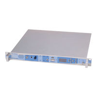
RE9010-2G
TELERAD RE9010-2G Manuals
Manuals and User Guides for TELERAD RE9010-2G. We have
1
TELERAD RE9010-2G manual available for free PDF download: Technical Manual
TELERAD RE9010-2G Technical Manual (179 pages)
Brand:
TELERAD
| Category:
Receiver
| Size: 9 MB
Table of Contents
Table of Contents
6
Chapter 1. Introduction
12
About Telerad
12
Targeted Users
12
About this Manual
12
Manual Structure
13
Conventions Used in this Manual
13
Safety Rules
14
Information Regarding Safety
14
Installation Requirements
14
Servicing
14
Ventilation
14
Water and Humidity
14
Protection through Earthing
15
Symbols Used
15
Safety Symbols
15
Operational Symbols
15
Safety Instructions
16
General
16
Electrical Risks
17
Risks Related to the Work Environment
24
Risks Related to Transportation
25
Transport and Storage
26
General Information
26
Packing - Pre-Packaging
26
Packaging
26
Hardware and Mechanical Elements
26
Desiccation
26
Marking
26
Transportation
27
Storage
27
Conformity
27
Reference Directives
27
Ce Certification
29
Equipment Traceability
29
Warranty
29
Copyright
30
Reference Documents
30
Chapter 2. Presentation
32
General
32
Presentation of the Equipment
33
Hardware and Operational Presentation
33
Presentation of Software
34
Different Versions
34
Sub-Assemblies
35
Sub-Assemblies Common to the Two Receivers
35
Sub-Assemblies Specific to the RE9000-2G
35
Sub-Assemblies Specific to the RE9010-2G
35
Options
35
RE9000-2G Options
35
RE9010-2G Options
36
Set of Mobile Plugs
36
Compatible Equipment
36
Equipment Characteristics
37
Electrical Characteristics
37
General Characteristics
37
Specifications for the RE9000-2G
38
A3E Specifications
38
F3E Specifications
39
Specifications for the RE9010-2G
40
A3E Specifications
40
F3E Specifications
41
Mechanical Characteristics
42
Climatic and Environmental Specifications
42
Chapter 3. Operational Description
44
Simplified Operation
44
Presentation
44
Architecture
44
Functional Description
45
Front Panel PCB (PAVR42101) Combined with the Display PCB (CLAF12164)
45
Chassis (CHRE43185)
45
Μp / DSP PCB (MIPR11006)
45
Control PCB (CNUM12163)
45
VHF Synthesizer Module (SVHF25077) (RE9000-2G Only)
46
UHF Synthesizer Module (SUHF25078) (RE9010-2G Only)
46
VHF Front End Module (VUFI23186) (RE9000-2G Only)
46
UHF Front End Module (VUFI23191) (RE9010-2G Only)
46
Power Supply Module (ALSE53005)
46
General Description
48
Presentation of the Front Panel
48
Chapter 4. Presentation of the Unit
49
Management of the " Alarm " Led Vs the Power Supply Voltage
50
Presentation of the Rear Panel
51
Description of Connectors
53
Front Panel Connectors
53
Maintenance Connector
53
Rear Panel Connectors
54
J1 Mains Power Supply Connector
54
J6 +24V BATTERY POWER SUPPLY Connector
54
J2 SUPERVISION Connector
55
J3 OPERATION Connector
56
J4 10Mhz INPUT Connector
58
J5 DATA Connector
58
J7 RF ANTENNA Connector
59
J14 and J15 ETHERNET Connectors
59
Grounding Terminal
59
Electrical Interfaces Used
59
Choice of Site
62
Unpacking
62
Electrical Protection of the Equipment
62
Protection through Earthing
62
Chapter 5. Installation - Configuration - Commissioning
63
Installation
63
Protection by Circuit Breakers
63
Configuration
63
Mechanical Installation
63
Description and Configuration of Jumpers and Switches
63
Cnum12163 Pcb
64
PAVR42101 Front Panel PCB
64
MIPR11006 Microcontroller / DSP PCB
64
CLAF12164 Screen/ Keyboard PCB, VUFI23186 VHF Receiver, VUFI23191 UHF Receiver, SVHF25077 VHF Synthesizer, SUHF25078 UHF Synthesizer and ALSE53005 Power Supply Modules
65
Assembly of Coaxial Relays
65
Minimum Connection for Commissioning
65
Connection in Transceiver Configuration
66
Basic Commissioning
68
Preliminary Adjustments
69
EQUIPMENT COMMISSIONING in Voip CONFIGURATION
69
Connection to a Network
70
Configuration of the Network Parameters
70
Configuration of the Operating Mode
70
Configuration of the SIP Parameters
70
Normal Users Name Listing
71
High Priority Users Name List
71
Commissioning
71
Equipment Commissioning in Snmp Configuration
72
Presentation
72
SNMP Protocol
72
Parameters to be Monitored and Controlled
72
Equipments Configuration
73
Procedure for Software Upload
74
Chapter 6. Operation
76
Presentation
76
Commands Accessible to the Operating Unit
76
Local Commands through the Screen/Keyboard Interface
76
Local Commands through the Rs232 Terminal
77
List of User Commands Accessible Without Login
77
List of User Commands Accessible with Administrator Login
78
Remote Commands through the JBUS Link
79
Commands Accessible in Read/Write
79
Commands Accessible in Read Only
79
Remote Commands through the SNMP Link
79
Local Operation of the Equipment
80
Local Commands through the Front Panel Screen/Keyboard Interface
80
Screen Operating
80
Keyboard Operation
83
Description of Commands
83
Main Menu
83
SQL" Menu
86
PRESET" Menu (Preset Channels)
87
PRESET / Select" Menu
88
PRESET / Create/Modify" Menu
89
PRESET / Clear" Menu
91
Clearing a Single Channel
92
Clearing All Channels
92
AUDIO" Menu
93
AUDIO/ANALOG" Menu
94
AUDIO/VOIP" Menu
95
MODE" Menu
96
Selection of A3E Mode
96
Selection of F3E Mode
97
Selection of ACARS or VDL2 Modes
97
Selection of G3E or VDL4 Modes
97
FREQ" Menu
98
SETUP" Menu
100
Setup / Hw Config." Menu
101
Setup / Hw Config./ ON/OFF" Menu
101
Setup / Hw Config./Comp" Menu
102
SETUP/ Display" Menu
103
Setup / Display / Language" Menu
104
Setup / Display / Brightness" Menu
105
SETUP / IP" Menu
106
SETUP/ IP/ ETH1" Menu
106
SETUP/ IP/ ETH2" Menu
107
SETUP / JBUS" Menu
109
SETUP/ Remote Ctrl" Menu
110
MAINT" Menu
111
MAINT / MEASURES" Menu
112
MAINT / TEST" Menu
113
MAINT / TEST / CBIT" Menu
114
MAINT / TEST / IBIT" Menu
114
MAINT / TEST / IBIT / LAUNCH IBIT" Menu
115
MAINT / TEST/ IBIT / IBIT RESULTS" Menu
116
MAINT / TCXO" Menu
117
MAINT / ABOUT" Menu
118
Local Operation through the Front Panel RS232 Interface
119
Remote Operation of Equipment
119
Remote Operation through the JBUS Link
119
Remote Operation through the SNMP Link
119
Maintenance
120
Maintenance Concept
120
Reminder of Safety Rules
120
Preventive Maintenance
120
Corrective Maintenance
120
Type of Protective Fuses
120
Corrective Maintenance Operations
121
Elements for Maintenance Help
121
ALSE53005 Power Supply Module
121
CLAF12164 Display PCB
121
CNUM12163 Control and Management PCB
121
MIPR11006 Microcontroller and DSP PCB
122
PAVR42101 Front Panel PCB
122
SVHF25077 or SUHF25078 Synthesizer Module
122
VUFI23186 or VUFI23191 RF Head PCB
122
Fault Localisation
122
Maintenance and Cleaning Operations
123
Frequency Table
123
Maintenance Operations Directory
123
List of Required Tools
123
E1 Guide Sheet
123
Disassembly / Reassembly Operations
124
Frequency Table
124
Maintenance Operations Directory
124
List of Required Tools
124
General Note Regarding Disassembly of Pcbs or Modules
124
D1 Guide Sheet
125
Guide Sheet D2
126
Guide Sheet D3
127
Guide Sheet D4
128
Guide Sheet D5
129
Guide Sheet D6
131
Guide Sheet D7
132
Operation Checks
133
Frequency Table
133
Maintenance Operations Directory
133
List of Required Measurement Devices
133
Guide Sheet V1
134
Guide Sheet V2
135
Adjustment Operations
141
Frequency Table
141
Maintenance Operations Directory
141
List of Required Tools
141
Guide Sheet R1
142
Guide Sheet R2
143
Guide Sheet R3
144
Parts List
146
St Level Parts List
146
Chapter 9. Diagrams
148
List of Photos
148
List of Mechanical Plates
148
List of Interconnection Plates
148
List of Block Diagram Plates
148
List of Layout View Slides
149
Appendix A. List of Abbreviations
150
Appendix B. Declaration of Conformity by a Notified Body
152
R&TTE Declaration of Conformity for the VHF Receiver RE9000A-2G
152
R&TTE Declaration of Conformity for the UHF Receiver RE9010A-2G
153
Advertisement
Advertisement
Related Products
TELERAD RE9000-2G
TELERAD Categories
Receiver
Transmitter
More TELERAD Manuals
Login
Sign In
OR
Sign in with Facebook
Sign in with Google
Upload manual
Upload from disk
Upload from URL