Table of Contents
Advertisement
Quick Links
Advertisement
Table of Contents

Summary of Contents for TELERAD RE9000-2G
- Page 2 Date rév. : 02/03/11 Rèf. s/ens. : RE9000A-2G Code s/ens. : 84500146 Code ens. : 80100067 Page : 1/1 Rèf. ens. : RE9000-2G email address TEL : +33 5 59 58 55 00 courrier@telerad.fr FAX : +33 5 59 58 55 01...
- Page 3 Code ens. : 80100070 Page : 1/1 Rèf. ens. : RE9010-2G email address TEL : +33 5 59 58 55 00 courrier@telerad.fr FAX : +33 5 59 58 55 01 2 Avenue de la butte aux cailles, B.P. 302 64603 ANGLET CEDEX FRANCE...
- Page 4 RE9000-2G VHF DIGITAL RECEIVER RE9010-2G UHF DIGITAL RECEIVER TECHNICAL MANUAL - 40500070 V1.08 LIST OF MODIFICATIONS REVISION PAGE(S) CORRECTED VISA DATE V1.00 Created on 16/02/11 16/02/11 V1.01 Updates 17/02/11 V1.02 Updates 09/03/11 V1.03 Translation to English and updates 08/04/11 V1.04 Updates pages A to 144.
- Page 5 RE9000-2G VHF DIGITAL RECEIVER RE9010-2G UHF DIGITAL RECEIVER TECHNICAL MANUAL - 40500070 V1.08 This page is left blank intentionally. 43001760 V1.08...
-
Page 6: Table Of Contents
Sub-assemblies ......................24 2.2.4.1 Sub-assemblies common to the two receivers ............24 2.2.4.2 Sub-assemblies specific to the RE9000-2G ............. 24 2.2.4.3 Sub-assemblies specific to the RE9010-2G .............. 24 2.2.5 Options ........................24 ... - Page 7 VHF synthesizer module (SVHF25077) (RE9000-2G only) ........35 3.1.3.6 UHF synthesizer module (SUHF25078) (RE9010-2G only) ........35 3.1.3.7 VHF front end module (VUFI23186) (RE9000-2G only) ........35 3.1.3.8 UHF front end module (VUFI23191) (RE9010-2G only) ........35 3.1.3.9 Power supply module (ALSE53005) ................
- Page 8 RE9000-2G VHF DIGITAL RECEIVER RE9010-2G UHF DIGITAL RECEIVER TECHNICAL MANUAL - 40500070 V1.08 5.3.2 PAVR42101 front panel PCB .................. 53 5.3.3 MIPR11006 microcontroller / DSP PCB ..............53 5.3.4 CLAF12164 screen/ keyboard PCB, VUFI23186 VHF receiver, VUFI23191 UHF ...
- Page 9 RE9000-2G VHF DIGITAL RECEIVER RE9010-2G UHF DIGITAL RECEIVER TECHNICAL MANUAL - 40500070 V1.08 6.3.1.3.6 "FREQ" Menu ......................87 6.3.1.3.7 "SETUP" Menu ......................89 6.3.1.3.7.1 "Setup / Hw Config." menu ..................89 6.3.1.3.7.1.1 "Setup / Hw config./ ON/OFF" menu............... 90 ...
- Page 10 RE9000-2G VHF DIGITAL RECEIVER RE9010-2G UHF DIGITAL RECEIVER TECHNICAL MANUAL - 40500070 V1.08 7.5.9 Guide sheet D5 ....................... 118 7.5.10 Guide sheet D6 ....................... 120 7.5.11 Guide sheet D7 ....................... 121 OPERATION CHECKS ..................122 ...
- Page 11 RE9000-2G VHF DIGITAL RECEIVER RE9010-2G UHF DIGITAL RECEIVER TECHNICAL MANUAL - 40500070 V1.08 LIST OF FIGURES Figure 1 - Front panel ............................37 Figure 2 – Jack connector for headphones ......................38 Figure 3 – Management of the « Alarm » led ......................39 ...
-
Page 12: Chapter 1. Introduction
CHAPTER 1. INTRODUCTION ABOUT TELERAD With over 40 years’ experience, TELERAD offers a very high quality range of Ground to Air radiocommunication equipment in the civil (VHF) or military (UHF) frequency range, as well as associated peripheral equipment. All this equipment is in compliance with the international standards in force and provides comprehensive, reliable and upgradeable system solutions. -
Page 13: Manual Structure
/ reassembly, verification and adjustment sheets. Chapter 8: Parts list. List at sub-assembly level of the components of the RE9000-2G VHF and RE9010-2G UHF receivers. Chapter 9: Plates. -
Page 14: Safety Rules
If these rules are not followed or the equipment is used for a purpose for which it is not designed (incorrect use), TELERAD cannot be held responsible for risks related to equipment damage or physical injury. -
Page 15: Protection Through Earthing
CHAP PTER 1 RE9000-2G V VHF DIGITAL L RECEIVER INTRO ODUCTION RE9010-2G U UHF DIGITAL L RECEIVER TECHNICA AL MANUAL - 4 40500070 V1.08 1.4.1 Prote ection throug gh earthing The t terminal on t the rear, iden ntified with th... -
Page 16: Safety Instructions
CHAPTER 1 RE900 00-2G VHF DI IGITAL RECE EIVER NTRODUCTION RE901 10-2G UHF DI IGITAL RECE EIVER TECHN NICAL MANUA L - 40500070 V V1.08 1.4.2 Oper rational symb bols Indicates tha at the equipm ment must b be supplied w with alternati ing current ( (AC) at the... -
Page 17: Electrical Risks
CHAP PTER 1 RE9000-2G V VHF DIGITAL L RECEIVER INTRO ODUCTION RE9010-2G U UHF DIGITAL L RECEIVER TECHNICA AL MANUAL - 4 40500070 V1.08 1.4.3 Elec trical risks PRESEN NCE OF HIG GH VOLTA High voltages ar e required w... - Page 18 If there is no such protection, this may result in damage to the equipment, destruction or a fire. PROTECTION OF MAINTENANCE STAFF Unless otherwise specified by TELERAD, the equipment must be powered off before any operations, with the power cord disconnected. Only certified, qualified and trained staff may open, adjust and replace the PCBs or equipment modules.
- Page 19 CHAP PTER 1 RE9000-2G V VHF DIGITAL L RECEIVER INTRO ODUCTION RE9010-2G U UHF DIGITAL L RECEIVER TECHNICA AL MANUAL - 4 40500070 V1.08 ROTECTIO N AGAINS T ELECTR ROSTATIC DISCHARG GE (ESD) The c certified staf ff replacing the PCB or...
- Page 20 CHAPTER 1 RE900 00-2G VHF DI IGITAL RECE EIVER NTRODUCTION RE901 10-2G UHF DI IGITAL RECE EIVER TECHN NICAL MANUA L - 40500070 V V1.08 If t the victim d does not resp pond, they ar re unconscio ous. You mus st check their r breathing: loosen the...
- Page 21 CHAP PTER 1 RE9000-2G V VHF DIGITAL L RECEIVER INTRO ODUCTION RE9010-2G U UHF DIGITAL L RECEIVER TECHNICA AL MANUAL - 4 40500070 V1.08 RECO OVERY PO SITION Place e yourself o n the side t towards neel by thei ir waist.
- Page 22 CHAPTER 1 RE900 00-2G VHF DI IGITAL RECE EIVER NTRODUCTION RE901 10-2G UHF DI IGITAL RECE EIVER TECHN NICAL MANUA L - 40500070 V V1.08 UTH TO MO OUTH Kneel ne ext to the vict tim, near the eir face. With you ur hand plac ed on the vi...
- Page 23 CHAP PTER 1 RE9000-2G V VHF DIGITAL L RECEIVER INTRO ODUCTION RE9010-2G U UHF DIGITAL L RECEIVER TECHNICA AL MANUAL - 4 40500070 V1.08 ERNAL CA ARDIAC MA ASSAGE As fa far as possibl le, bare the v ictim’s chest...
-
Page 24: Risks Related To The Work Environment
CHAPTER 1 RE900 00-2G VHF DI IGITAL RECE EIVER NTRODUCTION RE901 10-2G UHF DI IGITAL RECE EIVER TECHN NICAL MANUA L - 40500070 V V1.08 1.4.3 Risk ks related to t the work env vironment EXPL OSIVE ATM MOSPHER Do n ot use the eq quipment in the presence... -
Page 25: Risks Related To Transportation
1.4.3.4 Risks related to transportation HANDLING Certain equipment designed by TELERAD may be very heavy. In this case do not transport the equipment without using appropriate lifting devices. Refer to the mechanical characteristics of the equipment for information on its weight. -
Page 26: Transport And Storage
CHAPTER 1 RE900 00-2G VHF DI IGITAL RECE EIVER NTRODUCTION RE901 10-2G UHF DI IGITAL RECE EIVER TECHN NICAL MANUA L - 40500070 V V1.08 ANSPORT A AND STORA RAGE 1.5.1 eral inform ation Given n the great d diversity of s structures, re egulations, w weather cond... -
Page 27: Transportation
Keep equipment in its original packaging until used, and do not pile up equipment haphazardly. CONFORMITY The VHF RE9000-2G and UHF RE9010-2G are compliant with the standards currently in force relating to EMC, low voltage, radiocommunication, and worker safety aspects. 1.6.1 Reference directives ... - Page 28 RE9000-2G VHF DIGITAL RECEIVER CHAPTER 1 INTRODUCTION RE9010-2G UHF DIGITAL RECEIVER TECHNICAL MANUAL - 40500070 V1.08 Associated standards: EN 300 676-1 V1.5.1 (07/2010): Electromagnetic compatibility and radio spectrum matters (ERM). Ground-based VHF hand-held, mobile and fixed radio transmitters, receivers and transceivers for the VHF aeronautical mobile service using amplitude modulation –...
-
Page 29: Ce Certification
CHAP PTER 1 RE9000-2G V VHF DIGITAL L RECEIVER INTRO ODUCTION RE9010-2G U UHF DIGITAL L RECEIVER TECHNICA AL MANUAL - 4 40500070 V1.08 Worker sa afety: Directive 2 2004/40/EC on the minim mum health and safety r requirements... -
Page 30: Copyright
RE9010-2G UHF DIGITAL RECEIVER TECHNICAL MANUAL - 40500070 V1.08 COPYRIGHT This manual is the property of TELERAD. All rights reserved. It shall not be reproduced in any form without the prior written permission of TELERAD. 2010, Télérad. All rights reserved. - Page 31 CHAPTER 1 RE9000-2G VHF DIGITAL RECEIVER INTRODUCTION RE9010-2G UHF DIGITAL RECEIVER TECHNICAL MANUAL - 40500070 V1.08 This page is left blank intentionally. 43001760 V1.08...
-
Page 32: Chapter 2. Presentation
CHAPTER 2. PRESENTATION GENERAL The multi-mode RE9000-2G VHF and RE9010-2G UHF receivers have been developed to fulfil new civil aviation voice and data reception telecommunications requirements, firstly, in the 118-144MHz frequency range, can be optionally extended to 112-156MHz, and secondly for military aviation telecommunications, in the 225-400MHz frequency range, can be optionally extended to 225- 406.1MHz with the F3E option. -
Page 33: Presentation Of The Equipment
It is linked to the control PCB by two ribbon cables. The front end receiver module, VHF for the RE9000-2G, UHF for the RE9010-2G, located at the front of the equipment. It is also linked to the control PCB by a ribbon cable. -
Page 34: Presentation Of Software
2.2.2 Presentation of software The onboard software in the multi-mode RE9000-2G VHF or RE9010-2G UHF receiver is designed around a real-time multi-process kernel used by the microcontroller of the Microprocessor/DSP module. After reading the configuration parameters, the microcontroller downloads the DSP software into its memory. -
Page 35: Sub-Assemblies
53500016 µP processing and DSP AC/DC power supply (RE9000A-2G and ALSE53005 58500064 Internal 24V supply RE9010A-2G versions only) 2.2.4.2 Sub-assemblies specific to the RE9000-2G Reference Name TLD code Description SVHF25077 VHF synthesizer 52000620 Generation of local oscillator VUFI23186 VHF reception module... -
Page 36: Re9010-2G Options
RE9000-2G VHF DIGITAL RECEIVER CHAPTER 2 PRESENTATION RE9010-2G UHF DIGITAL RECEIVER TECHNICAL MANUAL - 40500070 V1.08 2.2.5.2 RE9010-2G options Reference Name TLD code Option type Description Multi-mode UHF receiver with mains Option A RE9010A-2G 84500148 Compulsory and battery inputs. Multi-mode UHF receiver with... -
Page 37: Equipment Characteristics
CHAPTER 2 RE9000-2G VHF DIGITAL RECEIVER PRESENTATION RE9010-2G UHF DIGITAL RECEIVER TECHNICAL MANUAL - 40500070 V1.08 EQUIPMENT CHARACTERISTICS 2.3.1 Electrical characteristics 2.3.1.1 General characteristics Characteristics Value Operating modes .... : RE9000-2G VHF receiver: RE9010-2G UHF receiver: Basic: A3E. Basic: A3E. -
Page 38: Specifications For The Re9000-2G
RE9000-2G VHF DIGITAL RECEIVER CHAPTER 2 PRESENTATION RE9010-2G UHF DIGITAL RECEIVER TECHNICAL MANUAL - 40500070 V1.08 2.3.1.2 Specifications for the RE9000-2G 2.3.1.2.1 A3E specifications Measurement conditions as per EN 300 676-1 V1.5.1 and EN 300 676-2 V1.4.1 ETSI standards. Characteristics Value Mode ........ -
Page 39: F3E Specifications
F3E specifications Measurement conditions as per EN 300 086-1 V1.4.1 ETSI standard. Note: Do not take the following electrical characteristics into account if the F3E option has not been installed in the RE9000-2G receiver. Characteristics Value Mode ..........: F3E. -
Page 40: Specifications For The Re9010-2G
RE9000-2G VHF DIGITAL RECEIVER CHAPTER 2 PRESENTATION RE9010-2G UHF DIGITAL RECEIVER TECHNICAL MANUAL - 40500070 V1.08 2.3.1.3 Specifications for the RE9010-2G 2.3.1.3.1 A3E specifications Measurement conditions as per EN 302 617-1 V1.1.1 and EN 302 617-2 V1.5.1 ETSI standards for the 25kHz channels. -
Page 41: F3E Specifications
CHAPTER 2 RE9000-2G VHF DIGITAL RECEIVER PRESENTATION RE9010-2G UHF DIGITAL RECEIVER TECHNICAL MANUAL - 40500070 V1.08 2.3.1.3.2 F3E specifications Measurement conditions as per EN 300 086-1 V1.4.1 ETSI standard. Note: Do not take the following electrical characteristics into account if the F3E option has not been installed in the RE9010-2G receiver. -
Page 42: Mechanical Characteristics
PRESENTATION RE9010-2G UHF DIGITAL RECEIVER TECHNICAL MANUAL - 40500070 V1.08 2.3.2 Mechanical characteristics Mechanical dimensions of RE9000-2G…..: see plate 45000061. Mechanical dimensions of RE9010-2G…..: see plate 45000065. Weight ..............: < 4 kg. 2.3.3 Climatic and environmental specifications Operating temperature ..........: between -20 and +55°C. - Page 43 CHAPTER 2 RE9000-2G VHF DIGITAL RECEIVER PRESENTATION RE9010-2G UHF DIGITAL RECEIVER TECHNICAL MANUAL - 40500070 V1.08 This page is left blank intentionally. 43001760 V1.08...
-
Page 44: Chapter 3. Operational Description
Voice over IP (VoIP). 3.1.2 Architecture The RE9000-2G and RE9010-2G receivers are made up of 8 PCBs and modules, each with a specific function: PCBs or Modules common to the 2 units: Description:... -
Page 45: Functional Description
The CNUM12163 PCB recovers the 21.4MHz IF signal coming from either the VUFI23186 PCB (RE9000-2G receiver), or the VUFI23191 PCB (RE9010-2G receiver), digitises it in a digital step- down converter box, then transmits the data obtained to the MIPR11006 PCB, where it will be analysed by the DSP. -
Page 46: Vhf Synthesizer Module (Svhf25077) (Re9000-2G Only)
TECHNICAL MANUAL - 40500070 V1.08 3.1.3.5 VHF synthesizer module (SVHF25077) (RE9000-2G only) Given the heterodyne structure of the RE9000-2G receiver, the SVHF25077 VHF synthesizer module supplies the local oscillator to the mixer of the VUFI23186 VHF head module. 3.1.3.6 UHF synthesizer module (SUHF25078) (RE9010-2G only) - Page 47 CHAPTER 3 RE9000-2G VHF DIGITAL RECEIVER OPERATIONAL DESCRIPTION RE9010-2G UHF DIGITAL RECEIVER TECHNICAL MANUAL - 40500070 V1.08 This page is left blank intentionally. 43001760 V1.08...
-
Page 48: General Description
CHAPTER 4 RE900 00-2G VHF DI IGITAL RECE EIVER RESENTATION N OF THE UNIT RE901 10-2G UHF DI IGITAL RECE EIVER TECHN NICAL MANUA L - 40500070 V V1.08 CHAPT TER 4. PRE ESENTATIO ON OF THE E UNIT NERAL DES SCRIPTION 4.1.1 Pres... -
Page 49: Chapter 4. Presentation Of The Unit
CHAPTER 4 RE9000-2G VHF DIGITAL RECEIVER PRESENTATION OF THE UNIT RE9010-2G UHF DIGITAL RECEIVER TECHNICAL MANUAL - 40500070 V1.08 Front panel component Description Indicator light Indicates squelch status. When it is on, squelch is SQUELCH active, when it is off, squelch is inhibited. -
Page 50: Management Of The " Alarm " Led Vs The Power Supply Voltage
CHAPTER 4 RE900 00-2G VHF DI IGITAL RECE EIVER RESENTATION N OF THE UNIT RE901 10-2G UHF DI IGITAL RECE EIVER TECHN NICAL MANUA L - 40500070 V V1.08 Front p panel compo onent Descrip iption: Screen n / Keyboard This lo ocal Man-Ma achine interfa... -
Page 51: Presentation Of The Rear Panel
CHAP PTER 4 RE9000-2G V VHF DIGITAL L RECEIVER PRESE ENTATION OF THE UNIT RE9010-2G U UHF DIGITAL L RECEIVER TECHNICA AL MANUAL - 4 40500070 V1.08 4.1.2 Pres sentation of the rear pan Figure 4 – Rea ar panel... - Page 52 CHAPTER 4 RE900 00-2G VHF DI IGITAL RECE EIVER RESENTATION N OF THE UNIT RE901 10-2G UHF DI IGITAL RECE EIVER TECHN NICAL MANUA L - 40500070 V V1.08 Rear p anel compon nent: Descrip iption Indicat tor light This i ndicator ligh ht is lit wh hen an exter...
-
Page 53: Description Of Connectors
Maintenance connector 9-contact female SUB-D connector ....DEP09S300… ..Ref. Telerad (150 00385) SUB-D 9 male contact mobile plug ....DEP09P……..Ref. Telerad (150 00023) Protective cover ..........8630-3637A ..Ref. Telerad (150 00152) The table below gives the list of signals available on this connector:... -
Page 54: Rear Panel Connectors
J6 +2 TTERY POW WER SUPPL Y connector 9-contact m male SUB-D connector ....DE EML5W ....Ref. Telerad (15 0 01156) 9-contact fe female SUB- D mobile plu ug ....DE EM 5W1S ....Ref. Telerad (15 0 01089) Protective c cover .. -
Page 55: J2 Supervision Connector
TECHNICAL MANUAL - 40500070 V1.08 4.2.2.3 J2 SUPERVISION connector 9-contact female SUB-D connector ....DEP09S500… ..Ref. Telerad (150 00503) SUB-D 9 male contact mobile plug ....DEP09P……..Ref. Telerad (150 00023) Protective cover ..........8630-3637A ..Ref. Telerad (150 00152) Signal No. I/O... -
Page 56: J3 Operation Connector
TECHNICAL MANUAL - 40500070 V1.08 4.2.2.4 J3 OPERATION connector 25-contact male SUB-D connector……….DEP25P-500 ....Ref. Telerad (150 00408) 25-contact female SUB-D mobile plug.….DEP25S ......Ref. Telerad (150 00275) Protective cover ..........8630-3639A ....Ref. Telerad (150 00153) Note: In the following table, the greyed contacts represent the minimum pin configuration required to operate the receiver. - Page 57 CHAPTER 4 RE9000-2G VHF DIGITAL RECEIVER PRESENTATION OF THE UNIT RE9010-2G UHF DIGITAL RECEIVER TECHNICAL MANUAL - 40500070 V1.08 Signal No. I/O Signal Characteristics Int. Transceiver Link RS485 output not inverted. Logical level: 0/5V. Desensitisation command. Acts on the receiver’s Receiver AGC command, to desensitise it.
-
Page 58: J4 10Mhz Input Connector
Used to connect an external 10 MHz reference. Level: 4 dBm ± 3dB. 4.2.2.6 J5 DATA connector 25-contact female SUB-D connector .....DBP-25S-500 ..Ref. Telerad (150 00229) SUB-D 25 male contact mobile plug .....DBP-25P ....Ref. Telerad (150 00149) Protective cover ..........8630-3639A……... Ref. Telerad (150 00153) Signal Signal Characteristics Int. -
Page 59: J7 Rf Antenna Connector
4.2.2.7 J7 RF ANTENNA connector Female BNC coaxial connector .....HO31 ....Ref. Telerad (160 00094) Male BNC coaxial mobile plug .....11BNC-50-3-16 ... Ref. Telerad (160.00323) Allows the receiver to be connected to an antenna through a suitable 50 coaxial cable. - Page 60 RE9000-2G VHF DIGITAL RECEIVER CHAPTER 4 PRESENTATION OF THE UNIT RE9010-2G UHF DIGITAL RECEIVER TECHNICAL MANUAL - 40500070 V1.08 1 1 5 1 1 4 1 14 1 1 5 6,8V 6,8V 220k 10 10 Sortie Entrée Receiver Entrée...
- Page 61 CHAPTER 4 RE9000-2G VHF DIGITAL RECEIVER PRESENTATION OF THE UNIT RE9010-2G UHF DIGITAL RECEIVER TECHNICAL MANUAL - 40500070 V1.08 This page is left blank intentionally. 43001760 V1.08...
-
Page 62: Choice Of Site
RE E9000-2G or RE90 010-2G recei iver. 5.2.1 packing The R RE9000-2G or RE9010- 2G receiver is delivered in packagin ng intended t to protect it from shocks that o occur during handling, an... -
Page 63: Chapter 5. Installation - Configuration - Commissioning
5.2.2.2 Protection by circuit breakers In order to comply with the electrical safety rules, the power supply inputs of the RE9000-2G or RE9010-2G receiver must be protected by external circuit breakers. The following table indicates the recommended range and type of circuit breaker:... -
Page 64: Cnum12163 Pcb
CHAPTER 5 RE900 00-2G VHF DI IGITAL RECE EIVER INSTALLATIO ON – CONFIGU URATION – CO OMMISSIONING RE901 10-2G UHF DI IGITAL RECE EIVER TECHN NICAL MANUA L - 40500070 V V1.08 SCRIPTION N AND CON NFIGURAT ION OF JU UMPERS AN ND SWITCH 5.3.1... -
Page 65: Claf12164 Screen/ Keyboard Pcb, Vufi23186 Vhf Receiver, Vufi23191 Uhf Receiver, Svhf25077 Vhf Synthesizer, Suhf25078 Uhf Synthesizer And Alse53005 Power Supply Modules
CHAP PTER 5 RE9000-2G V VHF DIGITAL L RECEIVER INSTA ALLATION – CO ONFIGURATION N – COMMISSIO ONING RE9010-2G U UHF DIGITAL L RECEIVER TECHNICA AL MANUAL - 4 40500070 V1.08 5.3.4 AF12164 scr reen/ keyboa ard PCB, VU UFI23186 V... -
Page 66: Connection In Transceiver Configuration
CHAPTER 5 RE900 00-2G VHF DI IGITAL RECE EIVER INSTALLATIO ON – CONFIGU URATION – CO OMMISSIONING RE901 10-2G UHF DI IGITAL RECE EIVER TECHN NICAL MANUA L - 40500070 V V1.08 NNECTION N IN TRANS SCEIVER C CONFIGUR RATION When n using the r receiver in T... - Page 67 CHAPTER 5 RE9000-2G VHF DIGITAL RECEIVER INSTALLATION – CONFIGURATION – COMMISSIONING RE9010-2G UHF DIGITAL RECEIVER TECHNICAL MANUAL - 40500070 V1.08 Configuration 2: use of an external antenna coaxial relay, combined with a transmission/reception antenna. Transmission / Reception antenna Power supply / Control...
-
Page 68: Basic Commissioning
TECHN NICAL MANUA L - 40500070 V V1.08 SIC COMM ISSIONING In the e case of the e RE9000-2G G or RE901 10A-2G rece eiver, once th he rear pane el connection ns are made, check k that the ye ellow "Mains... -
Page 69: Preliminary Adjustments
This adjustment is made through software, using the front panel screen / keyboard interface (see § 7.7.4 Adjustment sheet R1: “Adjusting the local oscillator”). EQUIPMENT COMMISSIONING IN VoIP CONFIGURATION: The commissioning of the RE9000-2G or RE9010-2G receiver in VoIP configuration needs to follow the next steps : Connection to network, ... -
Page 70: Connection To A Network
So the SIP protocol parameters must be defined during the communication setting. A difference with the previous parameters is that these ones are available only by using the RS232 terminal. 1. Define the name of RE9000-2G or RE9010-2G receiver such as the SIP user : o SIP USERNAME <name of the EM9000-2G or EM9010-2G>... -
Page 71: Normal Users Name Listing
This paragraph defines an users name list corresponding to the VCSS having a Normal priority, that can communicate with the RE9000-2G or RE9010-2G receiver, through Adding and Suppressing controls. These parameters are available only by using an RS232 terminal : 1. -
Page 72: Equipment Commissioning In Snmp Configuration
5.10.2 SNMP protocol The equipments are compliant with the 3 versions of SNMP Protocol (v1, v2c and v3). The MIB used by the SNMP agent on the RE9000-2G or RE9010-2G receiver is available in the following file: TELERAD-RE90X02G-MIB.TXT For transmitters of 9000-2G series 5.10.3... -
Page 73: Equipments Configuration
CHAPTER 5 RE9000-2G VHF DIGITAL RECEIVER INSTALLATION – CONFIGURATION – COMMISSIONING RE9010-2G UHF DIGITAL RECEIVER TECHNICAL MANUAL - 40500070 V1.08 Tests : used to visualize the tests reports, and run the tests on the equipments statusExternalCbit : External default outside the receiver detected... -
Page 74: Procedure For Software Upload
RE9000-2G VHF DIGITAL RECEIVER CHAPTER 5 INSTALLATION – CONFIGURATION – COMMISSIONING RE9010-2G UHF DIGITAL RECEIVER TECHNICAL MANUAL - 40500070 V1.08 5.11 PROCEDURE FOR SOFTWARE UPLOAD For more details about the procedure, please refer to the document [5] KITGB 40700003 V1.02 9000-2G Series : Document describing the procedure for uploading and/or releasing the software embedded into the MIDS11216 board, through a Web server interface. - Page 75 CHAPTER 5 RE9000-2G VHF DIGITAL RECEIVER INSTALLATION – CONFIGURATION – COMMISSIONING RE9010-2G UHF DIGITAL RECEIVER TECHNICAL MANUAL - 40500070 V1.08 This page is left blank intentionally. 43001760 V1.08...
-
Page 76: Chapter 6. Operation
RE9010-2G UHF DIGITAL RECEIVER TECHNICAL MANUAL - 40500070 V1.08 CHAPTER 6. OPERATION PRESENTATION This chapter provides the information required for programming and operating the RE9000-2G or RE9010-2G receiver: 1. Either locally: - via the front panel screen/keyboard, - via an RS232 terminal connected to the front panel Maintenance connector. -
Page 77: Local Commands Through The Rs232 Terminal
CHAPTER 6 RE9000-2G VHF DIGITAL RECEIVER OPERATION RE9010-2G UHF DIGITAL RECEIVER TECHNICAL MANUAL - 40500070 V1.08 Command Paragraph Remote ctl : Activation of remote control of the equipment 6.3.1.3.7.5 MAINT: Maintenance of the receiver 6.3.1.3.8 Measures : Measurements of the receiver 6.3.1.3.8.1... -
Page 78: List Of User Commands Accessible With Administrator Login
RE9000-2G VHF DIGITAL RECEIVER CHAPTER 6 OPERATION RE9010-2G UHF DIGITAL RECEIVER TECHNICAL MANUAL - 40500070 V1.08 Command Paragraph SQ : Squelch configuration (RF level and S/N ratio) 6.3.2 SQ? : Squelch status (RF level and S/N ratio) 6.3.2 STAT? : Status of the station 6.3.2... -
Page 79: Remote Commands Through The Jbus Link
CHAPTER 6 RE9000-2G VHF DIGITAL RECEIVER OPERATION RE9010-2G UHF DIGITAL RECEIVER TECHNICAL MANUAL - 40500070 V1.08 6.2.3 Remote commands through the JBUS link 6.2.3.1 Commands accessible in Read/Write Command Paragraph AF line level programming (0 to 7 for +10 to -11dBm by 3dB step) 6.4.1... -
Page 80: Local Operation Of The Equipment
/ keyboard interf face looks lik ke this : 6.3.1 Scre en operating The s screen of the e RE9000-2G G or RE9010 0-2G receive er is a 128x6 64 pixel OLE ED screen, 2 20x40mm in size, for which ea... - Page 81 CHAP PTER 6 RE9000-2G V VHF DIGITAL L RECEIVER OPERA RATION RE9010-2G U UHF DIGITAL L RECEIVER TECHNICA AL MANUAL - 4 40500070 V1.08 After r 5 minutes o of inactivity, , a standby m message is d displayed ran...
- Page 82 CHAPTER 6 RE900 00-2G VHF DI IGITAL RECE EIVER OPERATION RE901 10-2G UHF DI IGITAL RECE EIVER TECHN NICAL MANUA L - 40500070 V V1.08 There e are various s types of scr reens: Screen w with zones th at can be act tivated: (Exa mple: Main...
-
Page 83: Keyboard Operation
6.3.1.3.1 Main Menu When the RE9000-2G or RE9010-2G receiver is powered on, it first launches its startup sequence for a few seconds, then displays the main operating screen on the front panel display. This menu indicates the current operating parameters. - Page 84 CHAPTER 6 RE900 00-2G VHF DI IGITAL RECE EIVER OPERATION RE901 10-2G UHF DI IGITAL RECE EIVER TECHN NICAL MANUA L - 40500070 V V1.08 L Zone: Disp plays the pro ogrammed v value of the s squelch thres shold sele cted accordi ing to the car...
- Page 85 CHAPTER 6 RE9000-2G VHF DIGITAL RECEIVER OPERATION RE9010-2G UHF DIGITAL RECEIVER TECHNICAL MANUAL - 40500070 V1.08 The menu navigation flowchart is as follows: All channels Confirm Number Confirm (1 to 128) One channel Clear channel Mode SNR level Fréquence (0 to 5)
-
Page 86: Sql" Menu
CHAPTER 6 RE900 00-2G VHF DI IGITAL RECE EIVER OPERATION RE901 10-2G UHF DI IGITAL RECE EIVER TECHN NICAL MANUA L - 40500070 V V1.08 6.3.1. .3.2 "SQL L" Menu Purp ose: This m enu allows t the squelch p parameters to o be accesse d, selected a... -
Page 87: Preset" Menu (Preset Channels)
CHAP PTER 6 RE9000-2G V VHF DIGITAL L RECEIVER OPERA RATION RE9010-2G U UHF DIGITAL L RECEIVER TECHNICA AL MANUAL - 4 40500070 V1.08 Pres ss the key to valida ate the modi ifications rel lating to squ uelch, return to the... -
Page 88: Preset / Select" Menu
CHAPTER 6 RE900 00-2G VHF DI IGITAL RECE EIVER OPERATION RE901 10-2G UHF DI IGITAL RECE EIVER TECHN NICAL MANUA L - 40500070 V V1.08 6.3.1 .3.3.1 "PRE ESET / Selec ct" menu Purp ose: This su ub-menu allo ows a preset channel num mber to be se elected, in o... -
Page 89: Preset / Create/Modify" Menu
CHAP PTER 6 RE9000-2G V VHF DIGITAL L RECEIVER OPERA RATION RE9010-2G U UHF DIGITAL L RECEIVER TECHNICA AL MANUAL - 4 40500070 V1.08 6.3.1 .3.3.2 "PRE ESET / Crea ate/Modify" m menu Purp ose: This sub b-menu allow ... - Page 90 CHAPTER 6 RE900 00-2G VHF DI IGITAL RECE EIVER OPERATION RE901 10-2G UHF DI IGITAL RECE EIVER TECHN NICAL MANUA L - 40500070 V V1.08 If th his is a modi ification, the e screen disp plays: Usin ng the keys, se elect a chann nel number,...
-
Page 91: Preset / Clear" Menu
CHAP PTER 6 RE9000-2G V VHF DIGITAL L RECEIVER OPERA RATION RE9010-2G U UHF DIGITAL L RECEIVER TECHNICA AL MANUAL - 4 40500070 V1.08 6.3.1 .3.3.3 "PRE ESET / Clear r" menu Purp ose: This sub b-menu allow a preset cha... -
Page 92: Clearing A Single Channel
CHAPTER 6 RE900 00-2G VHF DI IGITAL RECE EIVER OPERATION RE901 10-2G UHF DI IGITAL RECE EIVER TECHN NICAL MANUA L - 40500070 V V1.08 6.3.1. 3.3.3.1 Clear ring a single c channel Pres ss the key to ente r the "Clear r one preset"... -
Page 93: Audio" Menu
CHAP PTER 6 RE9000-2G V VHF DIGITAL L RECEIVER OPERA RATION RE9010-2G U UHF DIGITAL L RECEIVER TECHNICA AL MANUAL - 4 40500070 V1.08 6.3.1. .3.4 "AUD UDIO" Menu Purp ose: This me enu allows th he type of AF... -
Page 94: Audio/Analog" Menu
CHAPTER 6 RE900 00-2G VHF DI IGITAL RECE EIVER OPERATION RE901 10-2G UHF DI IGITAL RECE EIVER TECHN NICAL MANUA L - 40500070 V V1.08 6.3.1 .3.4.1 "AU UDIO/ANAL OG" menu Purp ose: This m enu allows t the type of a analog AF to o be selected , as well as i... -
Page 95: Audio/Voip" Menu
CHAP PTER 6 RE9000-2G V VHF DIGITAL L RECEIVER OPERA RATION RE9010-2G U UHF DIGITAL L RECEIVER TECHNICA AL MANUAL - 4 40500070 V1.08 6.3.1 .3.4.2 "AU UDIO/VOIP" menu Purp ose: This m menu allows the type of VoIP AF, s... -
Page 96: Mode" Menu
CHAPTER 6 RE900 00-2G VHF DI IGITAL RECE EIVER OPERATION RE901 10-2G UHF DI IGITAL RECE EIVER TECHN NICAL MANUA L - 40500070 V V1.08 6.3.1. .3.5 "MO ODE" Menu Purp ose: This me enu allows th he selected m modulation m mode for oper ration of the... -
Page 97: Selection Of F3E Mode
CHAP PTER 6 RE9000-2G V VHF DIGITAL L RECEIVER OPERA RATION RE9010-2G U UHF DIGITAL L RECEIVER TECHNICA AL MANUAL - 4 40500070 V1.08 6.3.1 .3.5.2 Selec ction of F3E E mode Usin ng the ys on the key yboard, selec ct the "F3E... -
Page 98: Freq" Menu
RE9000-2G VHF DIGITAL RECEIVER CHAPTER 6 OPERATION RE9010-2G UHF DIGITAL RECEIVER TECHNICAL MANUAL - 40500070 V1.08 6.3.1.3.6 "FREQ" Menu Purpose: This menu allows the receiver’s operational frequency to be entered. This must comply with the ICAO recommendation, Appendix 10, relating to coding of frequencies as a function of the operating channel widths and the modulation mode. - Page 99 CHAP PTER 6 RE9000-2G V VHF DIGITAL L RECEIVER OPERA RATION RE9010-2G U UHF DIGITAL L RECEIVER TECHNICA AL MANUAL - 4 40500070 V1.08 Proce edure: The p procedure to access the "F FREQ" menu u is as follow Usin...
-
Page 100: Setup" Menu
CHAPTER 6 RE900 00-2G VHF DI IGITAL RECE EIVER OPERATION RE901 10-2G UHF DI IGITAL RECE EIVER TECHN NICAL MANUA L - 40500070 V V1.08 6.3.1. .3.7 "SET TUP" Menu Purp ose: This m menu allows c configuration n of the rece eiver parame eters not dir rectly linked... -
Page 101: Setup / Hw Config." Menu
CHAP PTER 6 RE9000-2G V VHF DIGITAL L RECEIVER OPERA RATION RE9010-2G U UHF DIGITAL L RECEIVER TECHNICA AL MANUAL - 4 40500070 V1.08 6.3.1. 3.7.1.1 "Setu up / Hw config g./ ON/OFF" m menu Objet t : The purpo... -
Page 102: Setup / Hw Config./Comp" Menu
CHAPTER 6 RE900 00-2G VHF DI IGITAL RECE EIVER OPERATION RE901 10-2G UHF DI IGITAL RECE EIVER TECHN NICAL MANUA L - 40500070 V V1.08 6.3.1. 3.7.1.2 "Setu up / Hw config g./COMP" me Purp ose: The pur rpose of this menu is to a activate or de eactivate the... -
Page 103: Setup/ Display" Menu
CHAP PTER 6 RE9000-2G V VHF DIGITAL L RECEIVER OPERA RATION RE9010-2G U UHF DIGITAL L RECEIVER TECHNICA AL MANUAL - 4 40500070 V1.08 6.3.1 .3.7.2 "SET TUP/ Display y" menu Purp ose: The pur rpose of this menu is to: ... -
Page 104: Setup / Display / Language" Menu
CHAPTER 6 RE900 00-2G VHF DI IGITAL RECE EIVER OPERATION RE901 10-2G UHF DI IGITAL RECE EIVER TECHN NICAL MANUA L - 40500070 V V1.08 6.3.1. 3.7.2.1 "Setu up / Display / Language" m menu Purp ose: The pur rpose of this menu is to s select the me nu display la... -
Page 105: Setup / Display / Brightness" Menu
CHAP PTER 6 RE9000-2G V VHF DIGITAL L RECEIVER OPERA RATION RE9010-2G U UHF DIGITAL L RECEIVER TECHNICA AL MANUAL - 4 40500070 V1.08 6.3.1. 3.7.2.2 "Setu up / Display / Brightness" m menu Purp ose: The pur rpose of this... -
Page 106: Setup / Ip" Menu
CHAPTER 6 RE900 00-2G VHF DI IGITAL RECE EIVER OPERATION RE901 10-2G UHF DI IGITAL RECE EIVER TECHN NICAL MANUA L - 40500070 V V1.08 6.3.1 .3.7.3 "SET TUP / IP" me Purp ose: The pu urpose of th his menu is s to configu ure the IP p parameters, u... -
Page 107: Setup/ Ip/ Eth2" Menu
CHAP PTER 6 RE9000-2G V VHF DIGITAL L RECEIVER OPERA RATION RE9010-2G U UHF DIGITAL L RECEIVER TECHNICA AL MANUAL - 4 40500070 V1.08 Ente er the "IP CONFIGUR RATION" m menu as pe er the proce edure desc cribed in § 6 6.3.1.3.7.3... - Page 108 CHAPTER 6 RE900 00-2G VHF DI IGITAL RECE EIVER OPERATION RE901 10-2G UHF DI IGITAL RECE EIVER TECHN NICAL MANUA L - 40500070 V V1.08 Value e: The param meters associ iated with the e "ETH2" m menu are: Value Mask Fixes the I IP address ac...
-
Page 109: Setup / Jbus" Menu
CHAP PTER 6 RE9000-2G V VHF DIGITAL L RECEIVER OPERA RATION RE9010-2G U UHF DIGITAL L RECEIVER TECHNICA AL MANUAL - 4 40500070 V1.08 6.3.1 .3.7.4 "SET TUP / JBUS" " menu Purp ose: The pu urpose of this s menu is to... -
Page 110: Setup/ Remote Ctrl" Menu
CHAPTER 6 RE900 00-2G VHF DI IGITAL RECE EIVER OPERATION RE901 10-2G UHF DI IGITAL RECE EIVER TECHN NICAL MANUA L - 40500070 V V1.08 6.3.1 .3.7.5 "SET TUP/ Remot e ctrl" menu Purp ose: The pu urpose of thi s menu is to o place the r radio equipm... -
Page 111: Maint" Menu
CHAP PTER 6 RE9000-2G V VHF DIGITAL L RECEIVER OPERA RATION RE9010-2G U UHF DIGITAL L RECEIVER TECHNICA AL MANUAL - 4 40500070 V1.08 6.3.1. .3.8 "MA AINT" Menu Purp ose: This me enu allows: equip pment maint tenance help... -
Page 112: Maint / Measures" Menu
CHAPTER 6 RE900 00-2G VHF DI IGITAL RECE EIVER OPERATION RE901 10-2G UHF DI IGITAL RECE EIVER TECHN NICAL MANUA L - 40500070 V V1.08 6.3.1 .3.8.1 "MA AINT / MEA SURES" me Purp ose: This me enu allows th he measurem ment screens to be accesse... -
Page 113: Maint / Test" Menu
CHAP PTER 6 RE9000-2G V VHF DIGITAL L RECEIVER OPERA RATION RE9010-2G U UHF DIGITAL L RECEIVER TECHNICA AL MANUAL - 4 40500070 V1.08 6.3.1 .3.8.2 "MA AINT / TEST T" menu Purp ose: This me enu allows tw wo types of t... -
Page 114: Maint / Test / Cbit" Menu
CHAPTER 6 RE900 00-2G VHF DI IGITAL RECE EIVER OPERATION RE901 10-2G UHF DI IGITAL RECE EIVER TECHN NICAL MANUA L - 40500070 V V1.08 6.3.1. 3.8.2.1 "MA AINT / TEST / / CBIT" menu Purp ose: This me enu allows th he result of th he transmitte er’s continuo... -
Page 115: Maint / Test / Ibit / Launch Ibit" Menu
CHAP PTER 6 RE9000-2G V VHF DIGITAL L RECEIVER OPERA RATION RE9010-2G U UHF DIGITAL L RECEIVER TECHNICA AL MANUAL - 4 40500070 V1.08 6.3.1. 3.8.2.2.1 " "MAINT / TE EST / IBIT / L LAUNCH IB BIT" menu Purp... -
Page 116: Maint / Test/ Ibit / Ibit Results" Menu
CHAPTER 6 RE900 00-2G VHF DI IGITAL RECE EIVER OPERATION RE901 10-2G UHF DI IGITAL RECE EIVER TECHN NICAL MANUA L - 40500070 V V1.08 6.3.1. 3.8.2.2.2 " "MAINT / TE EST/ IBIT / IB BIT RESULT TS" menu Purp ose: This me enu allows th he result of th... -
Page 117: Maint / Tcxo" Menu
CHAP PTER 6 RE9000-2G V VHF DIGITAL L RECEIVER OPERA RATION RE9010-2G U UHF DIGITAL L RECEIVER TECHNICA AL MANUAL - 4 40500070 V1.08 6.3.1 .3.8.3 "MA AINT / TCXO O" menu Purp ose: This m menu allows the accurac... -
Page 118: Maint / About" Menu
CHAPTER 6 RE900 00-2G VHF DI IGITAL RECE EIVER OPERATION RE901 10-2G UHF DI IGITAL RECE EIVER TECHN NICAL MANUA L - 40500070 V V1.08 6.3.1 .3.8.4 "MA AINT / ABOU UT" menu Purp ose: This me enu allows in nformation r relating to the e receiver to... -
Page 119: Local Operation Through The Front Panel Rs232 Interface
CHAPTER 6 RE9000-2G VHF DIGITAL RECEIVER OPERATION RE9010-2G UHF DIGITAL RECEIVER TECHNICAL MANUAL - 40500070 V1.08 6.3.2 Local operation through the front panel RS232 interface The front panel RS232 interface allows connection of either an RS232 terminal, or a PC emulating a terminal. -
Page 120: Maintenance
CHAPTER 7 RE900 00-2G VHF DI IGITAL RECE EIVER MAINTENANCE RE901 10-2G UHF DI IGITAL RECE EIVER TECHN NICAL MANUA L - 40500070 V V1.08 CHAPTER R 7. MAINT TENANCE INTENANC CE CONCEP 7.1.1 minder of saf fety rules Main ntenance ope erations may y result in h... -
Page 121: Corrective Maintenance Operations
CHAPTER 7 RE9000-2G VHF DIGITAL RECEIVER MAINTENANCE RE9010-2G UHF DIGITAL RECEIVER TECHNICAL MANUAL - 40500070 V1.08 7.1.3.2 Corrective maintenance operations Corrective maintenance involves the replacement of the defective PCBs (or modules) after a fault has been detected. Faults may be detected in a number of ways: ... -
Page 122: Mipr11006 Microcontroller And Dsp Pcb
RE9000-2G VHF DIGITAL RECEIVER CHAPTER 7 MAINTENANCE RE9010-2G UHF DIGITAL RECEIVER TECHNICAL MANUAL - 40500070 V1.08 7.2.4 MIPR11006 microcontroller and DSP PCB The following table indicates the indicator lights present on the PCB and their meaning: Indicator light Meaning Red light indicating µC "Hardware Reset"... -
Page 123: Maintenance And Cleaning Operations
CHAPTER 7 RE9000-2G VHF DIGITAL RECEIVER MAINTENANCE RE9010-2G UHF DIGITAL RECEIVER TECHNICAL MANUAL - 40500070 V1.08 MAINTENANCE AND CLEANING OPERATIONS 7.4.1 Frequency table Operations Frequency Cleaning the equipment Annually 7.4.2 Maintenance operations directory Sheet E1: Cleaning the equipment. 7.4.3 List of required tools ... -
Page 124: Disassembly / Reassembly Operations
7.5.4 eral note re garding disa assembly of f PCBs or m odules Unles ss otherwise indicated by y TELERAD, , before disa assembling a PCB or mod dule, always check k that the eq uipment is p powered off,... -
Page 125: D1 Guide Sheet
CHAPTER 7 RE9000-2G VHF DIGITAL RECEIVER MAINTENANCE RE9010-2G UHF DIGITAL RECEIVER TECHNICAL MANUAL - 40500070 V1.08 7.5.5 D1 guide sheet EQUIPMENT: MAINTENANCE SHEET RE9000-2G VHF DIGITAL RECEIVER RE9010-2G UHF DIGITAL RECEIVER Folio 1/1 SCOPE: Staff: Disassembly / Reassembly of RF front-end module VUFI23186 or... -
Page 126: Guide Sheet D2
RE9000-2G VHF DIGITAL RECEIVER CHAPTER 7 MAINTENANCE RE9010-2G UHF DIGITAL RECEIVER TECHNICAL MANUAL - 40500070 V1.08 7.5.6 Guide sheet D2 EQUIPMENT: MAINTENANCE SHEET RE9000-2G VHF DIGITAL RECEIVER RE9010-2G UHF DIGITAL RECEIVER Folio 1/1 SCOPE: Staff: Disassembly / Reassembly of front Panel PCB PAVR42101... -
Page 127: Guide Sheet D3
CHAP PTER 7 RE9000-2G V VHF DIGITAL L RECEIVER MAINT TENANCE RE9010-2G U UHF DIGITAL L RECEIVER TECHNICA AL MANUAL - 4 40500070 V1.08 7.5.7 Guid de sheet D3 UIPMENT: INTENANC CE SHEET RE90 000-2G VHF F DIGITAL R RECEIVER... -
Page 128: Guide Sheet D4
RE9000-2G VHF DIGITAL RECEIVER CHAPTER 7 MAINTENANCE RE9010-2G UHF DIGITAL RECEIVER TECHNICAL MANUAL - 40500070 V1.08 7.5.8 Guide sheet D4 EQUIPMENT: MAINTENANCE SHEET RE9000-2G VHF DIGITAL RECEIVER RE9010-2G UHF DIGITAL RECEIVER Folio 1/1 SCOPE: Staff: Disassembly / Reassembly of Power supply module ALSE53005... -
Page 129: Guide Sheet D5
CHAPTER 7 RE9000-2G VHF DIGITAL RECEIVER MAINTENANCE RE9010-2G UHF DIGITAL RECEIVER TECHNICAL MANUAL - 40500070 V1.08 7.5.9 Guide sheet D5 EQUIPMENT: MAINTENANCE SHEET RE9000-2G VHF DIGITAL RECEIVER RE9010-2G UHF DIGITAL RECEIVER Folio 1/2 SCOPE: Staff: Disassembly / Reassembly of control PCB CNUM12163... - Page 130 RE9000-2G VHF DIGITAL RECEIVER CHAPTER 7 MAINTENANCE RE9010-2G UHF DIGITAL RECEIVER TECHNICAL MANUAL - 40500070 V1.08 EQUIPMENT: MAINTENANCE SHEET RE9000-2G VHF DIGITAL RECEIVER RE9010-2G UHF DIGITAL RECEIVER Folio 2/2 SCOPE: Staff: Disassembly / Reassembly of control PCB CNUM12163 and 2 lines REASSEMBLY PROCEDURE: (cont.)
-
Page 131: Guide Sheet D6
CHAPTER 7 RE9000-2G VHF DIGITAL RECEIVER MAINTENANCE RE9010-2G UHF DIGITAL RECEIVER TECHNICAL MANUAL - 40500070 V1.08 7.5.10 Guide sheet D6 EQUIPMENT: MAINTENANCE SHEET RE9000-2G VHF DIGITAL RECEIVER RE9010-2G UHF DIGITAL RECEIVER Folio 1/1 SCOPE: Staff: Disassembly / Reassembly of microcontroller/DSP PCB MIPR11006... -
Page 132: Guide Sheet D7
RE9000-2G VHF DIGITAL RECEIVER CHAPTER 7 MAINTENANCE RE9010-2G UHF DIGITAL RECEIVER TECHNICAL MANUAL - 40500070 V1.08 7.5.11 Guide sheet D7 EQUIPMENT: MAINTENANCE SHEET RE9000-2G VHF DIGITAL RECEIVER RE9010-2G UHF DIGITAL RECEIVER Folio 1/1 SCOPE: Staff: Disassembly / Reassembly of Synthesizer module SVHF25077 or... -
Page 133: Operation Checks
CHAPTER 7 RE9000-2G VHF DIGITAL RECEIVER MAINTENANCE RE9010-2G UHF DIGITAL RECEIVER TECHNICAL MANUAL - 40500070 V1.08 OPERATION CHECKS 7.6.1 Frequency table Operations Frequency Brief check that the receiver works in AM mode Monthly Annually or In-depth check that the receiver works in AM mode after repair 7.6.2... -
Page 134: Guide Sheet V1
CHAPTER 7 RE900 00-2G VHF DI IGITAL RECE EIVER MAINTENANCE RE901 10-2G UHF DI IGITAL RECE EIVER TECHN NICAL MANUA L - 40500070 V V1.08 7.6.4 Guid de sheet V1 UIPMENT: INTENANC CE SHEET RE90 000-2G VH HF DIGITA L RECEIV RE90 010-2G UHF F DIGITAL R... -
Page 135: Guide Sheet V2
CHAPTER 7 RE9000-2G VHF DIGITAL RECEIVER MAINTENANCE RE9010-2G UHF DIGITAL RECEIVER TECHNICAL MANUAL - 40500070 V1.08 7.6.5 Guide sheet V2 EQUIPMENT: MAINTENANCE SHEET RE9000-2G VHF DIGITAL RECEIVER RE9010-2G UHF DIGITAL RECEIVER Folio 1/6 SCOPE: Staff: In-depth check that the receiver works in A3E mode... - Page 136 Checking operational frequency: Using the local screen/keyboard, set the receiver to the median frequency of 125MHz for the RE9000-2G, or 300MHz for the RE9010-2G, for a 25kHz channel (F = 125.000 or 300.000), then with the frequency meter, check the operational frequency of the receiver. If needed, adjust the frequency (see R1 adjustment procedure).
- Page 137 CHAPTER 7 RE9000-2G VHF DIGITAL RECEIVER MAINTENANCE RE9010-2G UHF DIGITAL RECEIVER TECHNICAL MANUAL - 40500070 V1.08 EQUIPMENT: MAINTENANCE SHEET RE9000-2G VHF DIGITAL RECEIVER RE9010-2G UHF DIGITAL RECEIVER Folio 3/6 SCOPE: Staff: In-depth check that the receiver works in A3E mode...
- Page 138 RE9000-2G VHF DIGITAL RECEIVER CHAPTER 7 MAINTENANCE RE9010-2G UHF DIGITAL RECEIVER TECHNICAL MANUAL - 40500070 V1.08 EQUIPMENT: MAINTENANCE SHEET RE9000-2G VHF DIGITAL RECEIVER RE9010-2G UHF DIGITAL RECEIVER Folio 4/6 SCOPE: Staff: In-depth check that the receiver works in A3E mode...
- Page 139 CHAPTER 7 RE9000-2G VHF DIGITAL RECEIVER MAINTENANCE RE9010-2G UHF DIGITAL RECEIVER TECHNICAL MANUAL - 40500070 V1.08 EQUIPMENT: MAINTENANCE SHEET RE9000-2G VHF DIGITAL RECEIVER RE9010-2G UHF DIGITAL RECEIVER Folio 5/6 SCOPE: Staff: In-depth check that the receiver works in A3E mode...
- Page 140 RE9000-2G VHF DIGITAL RECEIVER CHAPTER 7 MAINTENANCE RE9010-2G UHF DIGITAL RECEIVER TECHNICAL MANUAL - 40500070 V1.08 EQUIPMENT: MAINTENANCE SHEET RE9000-2G VHF DIGITAL RECEIVER RE9010-2G UHF DIGITAL RECEIVER Folio 6/6 SCOPE: Staff: In-depth check that the receiver works in A3E mode...
-
Page 141: Adjustment Operations
CHAPTER 7 RE9000-2G VHF DIGITAL RECEIVER MAINTENANCE RE9010-2G UHF DIGITAL RECEIVER TECHNICAL MANUAL - 40500070 V1.08 ADJUSTMENT OPERATIONS All the following adjustments may be carried out with the receiver in the rack or on a table. 7.7.1 Frequency table... -
Page 142: Guide Sheet R1
RE9000-2G VHF DIGITAL RECEIVER CHAPTER 7 MAINTENANCE RE9010-2G UHF DIGITAL RECEIVER TECHNICAL MANUAL - 40500070 V1.08 7.7.4 Guide sheet R1 EQUIPMENT: MAINTENANCE SHEET RE9000-2G VHF DIGITAL RECEIVER RE9010-2G UHF DIGITAL RECEIVER Folio 1/1 SCOPE: Staff: Local oscillator adjustment 1st and 2nd lines PRELIMINARY CONDITIONS ... -
Page 143: Guide Sheet R2
CHAPTER 7 RE9000-2G VHF DIGITAL RECEIVER MAINTENANCE RE9010-2G UHF DIGITAL RECEIVER TECHNICAL MANUAL - 40500070 V1.08 7.7.5 Guide sheet R2 EQUIPMENT: MAINTENANCE SHEET RE9000-2G VHF DIGITAL RECEIVER RE9010-2G UHF DIGITAL RECEIVER Folio 1/1 SCOPE: Staff: Squelch threshold adjustment and 2... -
Page 144: Guide Sheet R3
RE9000-2G VHF DIGITAL RECEIVER CHAPTER 7 MAINTENANCE RE9010-2G UHF DIGITAL RECEIVER TECHNICAL MANUAL - 40500070 V1.08 7.7.6 Guide sheet R3 EQUIPMENT: MAINTENANCE SHEET RE9000-2G VHF DIGITAL RECEIVER RE9010-2G UHF DIGITAL RECEIVER Folio 1/1 SCOPE: Staff: Output AF line level adjustment. - Page 145 CHAPTER 7 RE9000-2G VHF DIGITAL RECEIVER MAINTENANCE RE9010-2G UHF DIGITAL RECEIVER TECHNICAL MANUAL - 40500070 V1.08 This page is left blank intentionally. 43001760 V1.08...
-
Page 146: Parts List
RE9010-2G UHF DIGITAL RECEIVER TECHNICAL MANUAL - 40500070 V1.08 CHAPTER 8. PARTS LIST LEVEL PARTS LIST VHF DIGITAL RECEIVER ........... RE9000-2G ....(80100067) MECHANICAL CHASSIS ..........CHRE43185 ....(50001400) DISPLAY PCB ..............CLAF12164 ....(51001184) CONTROL PCB ..............CNUM12163 ....(51001182) INTERMEDIATE FREQUENCY MODULE .... - Page 147 CHAPTER 8 RE9000-2G VHF DIGITAL RECEIVER PARTS LIST RE9010-2G UHF DIGITAL RECEIVER TECHNICAL MANUAL - 40500070 V1.08 This page is left blank intentionally. 43001760 V1.08...
-
Page 148: Chapter 9. Diagrams
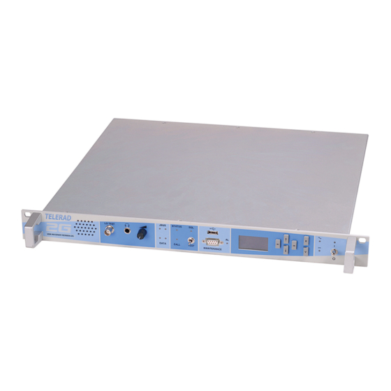
RE9000-2G VHF DIGITAL RECEIVER CHAPTER 9 DIAGRAMS RE9010-2G UHF DIGITAL RECEIVER TECHNICAL MANUAL - 40500070 V1.08 CHAPTER 9. DIAGRAMS LIST OF PHOTOS TELERAD Assembly or Name code Sub-assembly 44000267 ¾ view of VHF receiver RE9000A-2G RE9000A-2G 44000268 Front and Rear views of VHF receiver RE9000A-2G... -
Page 149: List Of Layout View Slides
CHAPTER 9 RE9000-2G VHF DIGITAL RECEIVER DIAGRAMS RE9010-2G UHF DIGITAL RECEIVER TECHNICAL MANUAL - 40500070 V1.08 LIST OF LAYOUT VIEW SLIDES TELERAD Assembly or Name code Sub-assembly SVHF25077 46500142 VHF or UHF synthesizer module layout diagram 1/1 SUHF25078 46500149 Control PCB layout diagram 1/1... -
Page 150: Appendix A. List Of Abbreviations
RE9000-2G VHF DIGITAL RECEIVER APPENDIX A LIST OF ABBREVIATIONS RE9010-2G UHF DIGITAL RECEIVER TECHNICAL MANUAL - 40500070 V1.08 APPENDIX A. LIST OF ABBREVIATIONS Acronym Description Alternating current ACARS Air Communication And Reporting System Analog-to-Digital Audio Frequency Automatic Gain Control Amplitude Modulation... - Page 151 APPENDIX A RE9000-2G VHF DIGITAL RECEIVER LIST OF ABBREVIATIONS RE9010-2G UHF DIGITAL RECEIVER TECHNICAL MANUAL - 40500070 V1.08 Acronym Description JTAG Joint Test Action Group Light-Emitting Diode Local Oscillator Low Voltage Media Access Control Management Memory Unit OLED Organic Light-Emitting Diode...
-
Page 152: Appendix B. Declaration Of Conformity By A Notified Body
APPENDIX B RE900 00-2G VHF DI IGITAL RECE EIVER DECLARATIO ON OF CONFOR RMITY BY A NO OTIFIED BODY RE901 10-2G UHF DI IGITAL RECE EIVER TECHN NICAL MANUA L - 40500070 V V1.08 APPENDIX X B. CLARATIO ON OF CON NFORMITY Y BY A NOT TIFIED BOD... -
Page 153: R&Tte Declaration Of Conformity For The Uhf Receiver Re9010A-2G
APPEN NDIX B RE9000-2G V VHF DIGITAL L RECEIVER DECLA ARATION OF C C ONFORMITY B BY A NOTIFIED D BODY RE9010-2G U UHF DIGITAL L RECEIVER TECHNICA AL MANUAL - 4 40500070 V1.08 B.2. R&TTE D Declaration of conformi i ty for the U... - Page 154 Indice rév. :V1.02 Front and rear views Date rév. : 02/03/11 Rèf. s/ens. : RE9000A-2G Code s/ens. : 84500146 Rèf. ens. : RE9000-2G Code ens. : 80100067 Page : 1/1 email address TEL : +33 5 59 58 55 00 courrier@telerad.fr...
- Page 155 VHF DIGITAL RECEIVER Indice rév. :V1.02 Top view Date rév. : 17/01/11 Rèf. s/ens. : RE9000A-2G Code s/ens. : 84500146 Rèf. ens. : RE9000-2G Code ens. : 80100067 Page : 1/1 email address TEL : +33 5 59 58 55 00 courrier@telerad.fr...
- Page 156 Rèf. ens. : RE9010-2G Code ens. : 80100070 Page : 1/1 email address TEL : +33 5 59 58 55 00 courrier@telerad.fr FAX : +33 5 59 58 55 01 2 Avenue de la butte aux cailles, B.P. 302 64603 ANGLET CEDEX FRANCE...
- Page 157 Rèf. ens. : RE9010-2G Code ens. : 80100070 email address TEL : +33 5 59 58 55 00 courrier@telerad.fr FAX : +33 5 59 58 55 01 2 Avenue de la butte aux cailles, B.P. 302 64603 ANGLET CEDEX FRANCE...
- Page 158 Mechanicals dimensions/weight (1/1) Rév. date : 08/07/2011 Réf. S/Ensemble : RE9000A-2G Code S/Ensemble : 84500146 Code Ensemble : 80100067 Réf. Ensemble : RE9000-2G RE9000C-2G 84500147 email address TEL: +33 5 59 58 55 00 courrier@telerad.fr 2 Avenue de la Butte aux Cailles, B.P.302 64603 ANGLET CEDEX FRANCE...
- Page 159 Code S/Ensemble : 84500148 Code Ensemble : 80100070 Réf. Ensemble : RE9010-2G RE9010C-2G 84500149 email address TEL: +33 5 59 58 55 00 courrier@telerad.fr 2 Avenue de la Butte aux Cailles, B.P.302 64603 ANGLET CEDEX FRANCE FAX: +33 5 59 58 55 01...
- Page 160 J 1 4 J 1 5 J 1 0 J 1 5 J 1 7 J 1 1 C N U M 1 2 1 6 3 J 1 4 J 1 2 J 1 6 C X 9 3 2 1 1 A L S E 5 3 0 0 5 R X L O V U F I 2 3 1 8 6...
- Page 161 J 1 4 J 1 5 J 1 0 J 1 5 J 1 7 J 1 1 C N U M 1 2 1 6 3 J 1 4 J 1 2 J 1 6 C X 9 3 2 1 1 A L S E 5 3 0 0 5 R X L O V U F I 2 3 1 9 1...
- Page 162 R 2 1 9 , C 1 5 7 R 4 8 , R 5 3 R 1 9 6 , C R 1 3 T P 1 4 R 1 6 5 , R 1 6 3 , C R 7 7 R 3 0 , C R 1 6 + 3 , 3 V P W R 2...
- Page 163 R 5 , C 2 M N 4 A + 3 , 3 V + 3 , 3 V L P f i l t e r R 1 3 , C 6 R 1 4 M N 4 E L P f i l t e r + 3 , 3 V + 3 , 3 V...
- Page 164 P A V R 4 2 1 0 1 b o a r d F r o n t p a n e l P A V R 4 2 1 0 1 b o a r d R 5 5 A F t o v o l u m e p o t e n t i o m e t e r J 1 - 1 4 C V 1...
- Page 165 E x t e r n a l 1 0 M H z E x t e r n a l 1 0 M H z D A T A l i n k O p e r a t i o n J B U S l i n k + 3 , 3 V E t h e r n e t 1...
- Page 166 M N 5 S h i f t r e g i s t e r s e n a b l e J 1 - 7 S C L R V H F S u b - V C O s p o w e r s u p p l y A L I M _ V C O V 1 A L I M _ V C O V 2 A L I M _ V C O V 3...
- Page 167 + 5 V J T A G T e s t b u s o f J T A G t e s t w i t h I 2 C b u s I 2 C b u s C T R L 1 1 2 1 7 L I N E A R S W I T C H I N G...
- Page 168 + 3 , 3 V p o w e r s u p p l y J 9 - 1 P W R 3 M N 1 C R 7 6 , R 8 V C C + 3 , 3 V µ...
- Page 169 M N 5 S h i f t r e g i s t e r s e n a b l e J 1 - 7 S C L R V H F S u b - V C O s p o w e r s u p p l y A L I M _ V C O U 1 A L I M _ V C O U 2 A L I M _ V C O U 3...
- Page 170 E x t e r n a l 1 0 M H z E x t e r n a l 1 0 M H z D A T A l i n k O p e r a t i o n J B U S l i n k P o w e r s u p p l y + 3 , 3 V...
- Page 171 M N 2 1 M N 1 6 M N 7 M N 9 M N 2 E T H 1 i n t e r f a c e M N 2 M N 1 3 J 1 4 E x t r a M X 7 I / O...
- Page 172 + 3 , 3 V p o w e r s u p p l y J 9 - 1 P W R 3 M N 1 C R 7 6 , R 8 V C C + 3 , 3 V µ...
- Page 173 4 6 5 0 0 1 4 2 V / U H F S Y N T H E S I Z E R B O A R D I n d e x r e v . : V 1 . 0 8 L a y o u t s s i d e A a n d B ( 1 / 1 ) D a t e r e v .
- Page 174 4 6 5 0 0 1 5 6 M I C R O - P R O C E S S O R / D S P B O A R D I n d e x r e v . : V 1 .
- Page 175 4 6 5 0 0 1 5 5 M I C R O - P R O C E S S O R / D S P B O A R D I n d e x r e v . : V 1 .
- Page 176 R E C E I V E R F R O N T P A N E L B O A R D 4 6 5 0 0 1 5 3 I n d e x r e v . : V 1 .
- Page 177 K E Y B O A R D A N D D I S P L A Y S C R E E N B O A R D 4 6 5 0 0 1 5 2 I n d e x r e v . : V 1 .
- Page 178 4 6 5 0 0 1 4 9 D I G I T A L B O A R D F O R R E C E P T I O N I n d e x r e v . : V 1 .
- Page 179 4 6 5 0 0 2 0 1 V H F - T O - D I G I T A L I F R E C E I V E R B O A R D I n d e x r e v . : V 1 .
Need help?
Do you have a question about the RE9000-2G and is the answer not in the manual?
Questions and answers