Sign In
Upload
Manuals
Brands
Teledyne Manuals
Digital Camera
Linea HS Series
Teledyne Linea HS Series Manuals
Manuals and User Guides for Teledyne Linea HS Series. We have
2
Teledyne Linea HS Series manuals available for free PDF download: User Manual
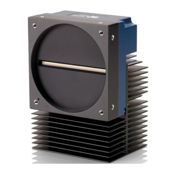
Teledyne Linea HS Series User Manual (127 pages)
Monochrome, Color and Multifield TDI Line Scan
Brand:
Teledyne
| Category:
Digital Camera
| Size: 3 MB
Table of Contents
Table of Contents
3
Figures
6
Linea Hs Series Cameras
8
Description
8
Color and Multifield Technology
9
Camera Highlights
10
Common Features
10
Resolution
10
Programmability
10
Applications
10
Part Numbers and Software Requirements
11
Specifications
13
Common Camera Specifications
13
Monochrome 300Khz Models
14
Monochrome 400Khz Models
15
Color and Multifield Models
16
Super Resolution Monochrome Model
17
Performance 1)
17
Environmental Specifications
17
Flash Memory Size
18
Certification & Compliance
18
Specifications: Monochrome Models
19
Responsivity & QE
19
Figure 1: 8K Monochrome Models Spectral Responsivity & QE
19
Figure 2: 16K Monochrome Models Spectral Responsivity & QE
20
Camera Input Power
21
Figure 3: Standard 8K Models Power Vs. Input Voltage
21
Figure 4: Standard 16K Models Power Vs. Input Voltage
21
Figure 5. HL-HM-16K40H-00-R Power Vs. Input Voltage
22
Specifications: Color Model
23
Responsivity & QE
23
Figure 6: Color Model Spectral Responsivity
23
Camera Input Power
24
Figure 7: Color Model QE
24
Figure 8: Color Model Power Vs. Input Voltage
24
Specifications: Multifield Model
25
Responsivity & QE
25
Figure 9: Multifield Model Spectral Responsivity
25
Camera Input Power
26
Figure 10: Multifield Model QE
26
Figure 11: Multifield Model Power Vs. Input Voltage
26
Specifications: Super Resolution 32K Model
27
Responsivity & QE
27
Figure 12: Super Resolution Model Spectral Responsivity & QE, 32K SR Mapped, 1X Gain
27
Camera Input Power
28
Figure 13. Super Resolution Model Power Vs. Input Voltage
28
Linea Hs Dark Current
29
Figure 14. Typical Dark Signal Vs. Line Rate
29
Figure 15. Line Period Vs. Dark Signal
30
Camera Processing Chain
31
Supported Industry Standards
31
Genicam
31
Figure 16: Digital Data Processing Chain
31
Camera Link HS
32
Figure 17: Linea HS Dual LC/SFP+ Connector Configuration
32
Figure 18: Single CLHS Connector Configuration
32
Data Cables
33
Mechanical Drawings
35
Figure 19: HL-FM-08K30H-00-R Mechanical Drawing
35
Figure 20: HL-HM-08K30H-00-R and HL-HM-08K40H-00-R Mechanical Drawing
36
Figure 21: HL-FM-16K15A-00-R Mechanical Drawing
37
Figure 22: HL-HM-16K30H-00-R, HL-HM-16K40H-00-R and HL-HF-16K10T-00-R Mechanical
38
Precautions
39
Electrostatic Discharge and the CMOS Sensor
39
Install & Configure Frame Grabber & Software
40
Using Sapera Camexpert
40
Camexpert Panes
41
Figure 23: Camexpert Frame Grabber Control Window
41
Setting up for Imaging
43
Camera I / O Connectors
43
Powering the Camera
43
Figure 24. Camera I / O Connectors: CX4 (Left) & LC Fiber Optic (Right)
43
Power and GPIO Connections
44
Figure 25: 12-Pin Hirose Pin Numbering
44
Figure 26: GPIO Cable Accessory #CR-GENC-IOP00
46
Establishing Camera Communications
47
Selecting the Data Format
47
Establishing Data Integrity
48
Camera Performance and Features
49
Synchronizing to Object Motion
49
Acquiring Images: Triggering the Camera
49
Measuring Line (Trigger) Rate
50
Maximum Line Rate
50
Minimum Line Rate
51
Scan Direction
51
Figure 27. Image with Incorrect Scan Direction
52
Camera Orientation
53
Figure 28: Example of Object Movement and Camera Direction
53
Spatial Correction
54
Figure 29: Spatial Correction
54
Figure 30. Standard and High-Speed Camera Line Spacing - Forward Scan Direction
55
Figure 31. Standard and High-Speed Camera Line Spacing - Reverse Scan Direction
56
Figure 32. Multifield Camera Line Spacing - Forward Scan Direction
57
Figure 33. Standard and High-Speed Camera Line Spacing - Reverse Scan Direction
58
Figure 34. Super Resolution Camera Line Spacing - Forward Scan Direction
59
Figure 35. Super Resolution Camera Line Spacing - Reverse Scan Direction
60
Alignment Markers
61
Figure 36: Alignment Markers
61
Parallax Correction: Using the Camera at Non-Perpendicular Angles to the Object
62
Figure 37: Camera Angle Parallax
62
Figure 38: Parallax Effect on Sensor Arrays Output
63
Imaging Modes
64
TDI Mode
64
High Dynamic Range (HDR)
65
High Full Well
65
Area Mode
65
Multifield Modes
65
32K Super Resolution Modes
66
Internal Trigger Mode
67
Establishing the Optimal Response
68
Exposure Control by Light Source Strobe
68
Figure 39: Strobe Timing
68
Figure 40 GPIO Functionality Block Diagram
70
Image Response Uniformity & Flat Field Calibration
71
Saving & Loading a PRNU Set Only
72
Setting Custom Flat Field Coefficients
72
Flat Field Calibration Filter
73
Flat Field Calibration Regions of Interest
73
Image Filters
74
Kernels
74
Image Filter Contrast Ratio
74
Figure 41: 1 X 3 Kernel
74
Figure 42: 1 X 5 Kernel
74
Binning
75
Figure 43: 2X2 Binning
75
Using Area of Interest (Aois)
76
Steps to Setup Area of Interest
77
Rules for Setting Areas of Interest
77
Enhancement of Interest (Eois) Regions
78
Figure 44: Enhancement of Interest
78
Customized Linearity Response (Lut)
79
How to Generate LUT with Camexpert
80
Adjusting Responsivity and Contrast Enhancement
82
Figure 45: Black Level, Gain and System Gain Processing Chain
82
Black Level
83
Changing Output Configuration
83
Pixel Format
83
Red Pixel Alignment
84
Figure 46: Red Pixel Artifacts
84
Figure 47: Align Red X Shift and Align Red y Shift
85
Red Shift X and y
85
Figure 48: Effect of Align Red X / y Shift Settings
86
Saving & Restoring Camera Setup Configurations
87
Figure 49. Relationship between Camera Settings
87
Active Settings for Current Operation
88
Default Setting
88
Factory Settings
88
User Setting
88
Appendix A: Genicam Commands
89
Camera Information Category
90
Camera Information Feature Descriptions
90
Figure 50 Example Camexpert Camera Information Panel
90
Built-In Self-Test Codes (BIST)
93
Camera Power-Up Configuration Selection Dialog
93
Camera Power-Up Configuration
93
Figure 51: Camexpert Power-Up Configuration Dialog
93
User Set Configuration Management
94
Camera Control Category
95
Camera Control Feature Descriptions
95
Figure 52: Camera Control Panel
95
Digital Io Control Category
99
Digital IO Control Feature Descriptions
99
Figure 53 Digital I/O Control Panel
99
Flat Field Category
102
Flat Field Control Feature Description
102
Figure 54: Flat Field Panel
102
Image Filter Mode
104
Image Format Control Category
105
Image Format Control Feature Description
105
Figure 55: Image Format Panel
105
File Access Control Category
108
File Access Control Feature Descriptions
108
Figure 56: File Access Control Panel
108
File Access Via the Camexpert Tool
110
Figure 57: File Access Control Tool
110
Figure 58: File Upload Completed Message Box
110
CLHS File Transfer Protocol
111
Upload File to Camera
112
Download a List of Camera Parameters
112
Transport Layer Control Category
113
Transport Layer Feature Descriptions
113
Figure 59: Transport Layer Panel
113
Acquisition and Transfer Control Category
115
Acquisition and Transfer Control Feature Descriptions
115
Figure 60: Acquisition & Transfer Control Panel
115
Appendix B: Trouble Shooting Guide
116
Diagnostic Tools
116
Figure 61: Camexpert Voltage & Temperature Features
116
Figure 62: Camexpert Test Pattern Feature
117
Resolving Camera Issues
119
Communications
119
Image Quality Issues
120
Power Supply Issues
123
Causes for Overheating & Power Shut down
124
Declarations of Conformity
125
FCC Statement of Conformance
125
CE Declaration of Conformity
125
Document Revision History
126
Contact Information
127
Sales Information
127
Technical Support
127
Advertisement
Teledyne Linea HS Series User Manual (124 pages)
Monochrome CMOS TDI Line Scan Cameras
Brand:
Teledyne
| Category:
Digital Camera
| Size: 4 MB
Table of Contents
Table of Contents
3
Linea Hs Monochrome Tdi Line Scan Cameras
7
Overview
7
Camera Highlights
8
Key Features
8
Programmability
8
Applications
8
Part Numbers
9
Hardware and Software Environments
10
Supported Industry Standards
11
Genicam
11
Camera Link HS
11
Specifications
12
Common Linea Hs Specifications
12
Environmental Specifications
13
Flash Memory Size
13
Certification & Compliance
13
Models Specifications
14
LC Fiber Optic Connector Models
14
CX4 Connector Models
15
Responsivity and Quantum Efficiency Graphs
18
Models 4K and 8K
18
Models 13K and 16K
18
Models 9K and 16K Backside Illuminated
19
Camera Input Power
20
Linea Hs Dark Current
22
Camera Pixel Arrangement
24
Camera Processing Chain
25
Installation
26
Handling Precautions
26
Preventing Operational Faults Due to Esd
27
Requirements
28
Frame Grabber
28
Camera Link HS Data Cable
28
Power Cable and Power Supply
29
Software and Device Driver
30
Quick Start Using a Teledyne Dalsa Frame Grabber
31
Installation Details
32
Installing Sapera LT
33
Installing the Frame Grabber Driver
33
Connecting and Powering up the Camera
34
Camera Status LED Indicator
35
Testing Acquisition
35
Selecting the Data Format
37
Using Camexpert with Linea HS
38
Camexpert Panes
38
Camexpert View Parameters Option
39
Overview of Tdi Technology
40
Arrays and Stages
40
Camera Performance and Features
42
Synchronizing to Object Motion
42
Triggering the Camera
42
Measuring Line (Trigger) Rate
43
Maximum Line Rate
43
Minimum Line Rate
44
Scan Direction
44
Spatial Correction
46
Alignment Markers
48
Imaging Modes
49
Tdi
49
TDI Stages
49
Tdi Hdr
49
Tdi Hfw
50
TDI Area
50
TDI Mode and Line Rate
50
Configuring the Frame Grabber for Different TDI Modes
50
Adjusting Responsivity and Contrast Enhancement with Black Level and Gain
52
Black Level
52
Gain
52
Establishing the Optimal Response
53
Exposure Control by Light Source Strobe
53
Flat Field Calibration
54
Dark Current Correction
56
Saving & Loading a PRNU Set Only
57
Custom Flat Field Coefficients
57
Flat Field Calibration Regions of Interest
57
Operating Backside Illumination Cameras at Low Line Rates
58
Image Filters
59
Kernels
59
Image Filter Contrast Ratio
59
Binning
60
Areas of Interest (Aois)
61
Rules for Setting Areas of Interest
61
Setting up Areas of Interest
62
Enhancement of Interest (Eois)
63
Customized Linearity Response (Lut)
64
How to Generate a LUT with Camexpert
64
Changing Output Pixel Format
67
Saving & Restoring Camera Setup Configurations
68
Camera Power-Up Configuration
68
Load / Save Configuration
68
Operational Reference
70
Camera Feature Categories
70
Camera Information Category
71
Camera Information Feature Descriptions
71
Built-In Self-Test Codes (BIST)
72
Camera Power-Up Configuration Selection Dialog
73
Camera Control Category
74
Camera Control Feature Descriptions
74
Digital Io Control Category
76
Digital IO Control Feature Descriptions
76
Flat Field Category
79
Flat Field Control Feature Description
79
Image Filter Mode
81
Image Format Category
82
Image Format Control Feature Description
82
File Access Control Category
85
File Access Control Feature Descriptions
85
File Access Control Dialog
86
CLHS File Transfer Protocol
87
Download a List of Camera Parameters
89
Transport Layer Control Category
90
Transport Layer Feature Descriptions
90
Acquisition and Transfer Control Category
92
Acquisition and Transfer Control Feature Descriptions
92
Technical Specifications
93
Labeling
93
Temperature Management
93
Mechanical Drawings
94
Connectors
98
Camera I/O Connectors
98
Powering the Camera
98
Power and GPIO Connections
99
Declarations of Conformity
102
FCC Statement of Conformance
102
CE Declaration of Conformity
102
Additional Reference Information
103
Optical Considerations
103
Illumination
103
Light Sources
103
Back Focal Variance When Using any Filter
103
Lens Modeling
104
Magnification and Resolution
104
Sensor Handling Instructions
106
Electrostatic Discharge and the Sensor
106
Protecting against Dust, Oil and Scratches
106
Cleaning the Sensor Window
106
Cleaning the Camera Housing Surface
107
Troubleshooting Guide
108
Diagnostic Tools
108
Camera Data File
108
Voltage & Temperature Measurement
108
Test Patterns - What Can They Indicate
109
Built-In Self-Test Codes
110
Resolving Camera Issues
111
Communications
111
Image Quality Issues
112
Power Supply Issues
114
Causes for Overheating & Power Shut down
114
Appendix
116
Performing Flat Field Calibration Using Camexpert
116
Flat Field Calibration White Target
116
Set up Dark and Bright Image Acquisitions with the Histogram Tool
116
Flat Field Correction Calibration
118
Revision History
123
Contact Information
124
Sales Information
124
Technical Support
124
Advertisement
Related Products
Teledyne Linea DALSA HS Series
Teledyne Lt-M1950B
Teledyne Lt-M2020B
Teledyne Lt-M3840B
Teledyne Lt-M4Q3QB
Teledyne Lt-C161QB
Teledyne Lt-C1630B
Teledyne Lt-C1980B
Teledyne Lt-C3200B
Teledyne Lt-C4020B
Teledyne Categories
Measuring Instruments
Analytical Instruments
Test Equipment
Digital Camera
Laboratory Equipment
More Teledyne Manuals
Login
Sign In
OR
Sign in with Facebook
Sign in with Google
Upload manual
Upload from disk
Upload from URL