Sign In
Upload
Manuals
Brands
Teledyne Manuals
Measuring Instruments
LightHawk 560DI
Teledyne LightHawk 560DI Manuals
Manuals and User Guides for Teledyne LightHawk 560DI. We have
1
Teledyne LightHawk 560DI manual available for free PDF download: Operation Manual
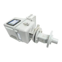
Teledyne LightHawk 560DI Operation Manual (183 pages)
Compliance Opacity Monitor
Brand:
Teledyne
| Category:
Measuring Instruments
| Size: 3 MB
Table of Contents
Table of Contents
5
System Overview
10
System Description, Standard Equipment
11
Optical Head Assembly
11
Retroreflector Assembly
12
Protective Purge Air System (Single)
12
Enhanced Remote Panel with Multi I/O Board
12
Ethernet Module
12
Calibration Kit
13
Attenuators
13
Hardware Kit
13
Specifications (Standard System)
14
Measurement Units
17
Correction for Exit Path Length
18
Safety
18
Optional Equipment
19
Protective Purge Air System (Dual)
19
Weather Cover, Retro
19
Purge Shutter Assemblies
19
Instrument Air Purge
19
High Efficiency Purge Air Filtration System
19
Hinged Fiberglass Weather Covers
20
Purge Air Heater
20
Optical Head Dust Cover
20
High Temperature Options
20
Optical Head Transport Cover
21
Alignment Scope, Mounting Flange
21
Optical Head Assembly
23
Overview
23
Mechanical Description
23
Optical Description
23
Electrical Description
24
AC Power Connections
24
Signal Processing Electronics
24
Simulated Zero/Upscale Device Drive Components
25
User Interface Description
26
Six Character LED Display
26
Key Pad
26
Individual Keys
26
Status Leds
29
Data Banks and Parameter Location Definitions
29
Enhanced Remote Panel with Multi I/Omodule
37
Overview
37
Mechanical Description
37
Electrical Description
38
Input Power Requirement
38
Circuit Description (Overview)
38
Operational Description
49
Main Display Screen
49
Main Menu Screen
52
Service Data Menu
52
View Service Data
52
View Head Mode
52
View Audit Data
52
Change Attenuator Values
53
Clear Audit Data
53
Status Codes Help
53
Output & Cal Tests
54
Output Module Configuration Menu
54
Analog Outputs 1,2
55
Analog Outputs 3,4
56
Relay Assignments
56
System Properties Menu
56
Change STP Ref Points
56
View System Properties
57
View Optics & Cal Properties
57
Change Cal Properties
57
Change Optics Properties
58
Change System Properties
58
Change Password
59
Change Opacity Set Points
59
Change Other Set Points
59
View Part. Mass Points
60
Change Part. Mass Curve
60
Display Properties Menu
61
View Alarm Set Points
62
View Trending Data
62
Trend Screen, Instantaneous Opacity
62
View Numerical Data
62
View Status History
63
View Alarms History
63
Overview
65
Analog Output Description
65
Analog Output Measurement Units Selection
65
Analog Output Current Range Selection
66
Automatic Calibration Analog Output Sequence
66
Discrete Isolator Inputs and JUMPER SETTINGS EFFECT on ANALOG OUTPUTS
67
Other Jumpers that Effect Analog Outputs
69
Relay Outputs
70
Analog Output Adjustment
70
Data Cables
71
Purge System Overview
77
Mechanical Description
77
Electrical Description
77
Operation
78
Purge Status
78
Dual Protective Purge Air System (Dual) Blower Option
78
Purge Shutter Assembly Option
78
Instrument Air Purge Option
79
Calibration Kit Overview
81
Operation
81
Storage
82
Maintenance & On-Stack Calibration
83
Routine Maintenance
83
On-Stack Calibration
87
Procedure for On-Stack Calibration Checklist
87
Attenuator Audit
94
Off-Stack Calibration
95
Factory Selection of Optical Elements
95
Generating an Optical Clear Path Opacity Signal
96
Simulating Installation Path Length on Test Stands
96
Actual Clear Path Conditions
97
Across Stack Alignment
97
Optical Head Assembly
97
Retroreflector Assembly
99
Cleaning the Optical Surfaces
100
Cleaning Materials
100
Cleaning Procedures
100
Optical Head Zero and One Hundred Percent Opacity
101
Setting the LED Current Level
101
Setting the Signal Gain
103
Final Calibration SET Function Routines
104
Adjusting Calibration Kit
110
Verify the Response of the Optical Head
112
Cal Mechanism Neutral Density Window Replacement
112
Cal Kit Neutral Density Window Replacement
114
Off-Stack Calibration History
116
Installation
118
Flange Mounting
118
Mounting Pipe Considerations
118
Distance Determination
120
Power Requirements
121
Purge Air System
121
Data Cable
121
Retro Purge Fail Cable
121
Mounting the Optical Head and Retro Assemblies
121
Enhanced Remote Display Assembly
122
Troubleshooting
124
Primary Status Code U3
124
Extended Status Code U4
125
Assistance
125
Site Specification Data Sheets
126
Maintenance Check Sheets
132
Lighthawk
136
Advertisement
Advertisement
Related Products
Teledyne 514
Teledyne 501 TRS
Teledyne 500268
Teledyne 500269
Teledyne 500270
Teledyne 500271
Teledyne LightHawk 560ES
Teledyne 5650
Teledyne LightHawk 560
Teledyne FLIR IIS Forge 5GigE FG-P5G-161S7
Teledyne Categories
Measuring Instruments
Analytical Instruments
Digital Camera
Test Equipment
Laboratory Equipment
More Teledyne Manuals
Login
Sign In
OR
Sign in with Facebook
Sign in with Google
Upload manual
Upload from disk
Upload from URL