Sign In
Upload
Manuals
Brands
Teledyne Analytical Instruments Manuals
Measuring Instruments
GFC 7002TU
Teledyne Analytical Instruments GFC 7002TU Manuals
Manuals and User Guides for Teledyne Analytical Instruments GFC 7002TU. We have
1
Teledyne Analytical Instruments GFC 7002TU manual available for free PDF download: Operation Manual
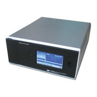
Teledyne Analytical Instruments GFC 7002TU Operation Manual (293 pages)
N2O Analyzer
Brand:
Teledyne Analytical Instruments
| Category:
Measuring Instruments
| Size: 11 MB
Table of Contents
About this Manual
4
Important Safety Information
6
Consignes de Sécurité
7
Table of Contents
8
Table of Contents
14
List of Figures
14
List of Tables
16
Part I General Information
18
Introduction, Features and Options
20
GFC7002T Family Overview
20
Features
21
GFC7002T/GFC7002TU Documentation
21
Options
21
Table 1-1: Analyzer Options
22
Figure 3-13: Concentration Alarm Relay
23
Specifications and Approvals
26
Specifications
26
Table 2-1: GFC7002T/GFC7002TU Basic Unit Specifications
26
EPA Equivalency Designation
27
Approvals and Certifications
27
Safety
27
Emc
27
Other Type Certifications
27
Getting Started
28
Unpacking the GFC7002T/GFC7002TU Analyzer
28
Ventilation Clearance
29
Table 3-1: Ventilation Clearance
29
Instrument Layout
30
Front Panel
30
Appendix A - Version Specific Software Documentation
30
Appendix B - Gfc7002T/Gfc7002Tu Spare Parts List
30
Appendix C - Repair Questionnaire - Gfc7002T
30
Appendix D - Schematics
30
Figure 3-1: Front Panel Layout
30
Figure 3-2: Display Screen and Touch Control
31
Table 3-2: Display Screen and Touch Control Description
32
Figure 3-3: Display/Touch Control Screen Mapped to Menu Charts
33
Figure 3-4: Rear Panel Layout
34
Rear Panel
34
GFC7002T/GFC7002TU Analyzer Layout
35
Table 3-3: Rear Panel Description
35
Figure 3-5: Internal Layout - GFC7002T
36
Figure 3-6: Internal Layout - GFC7002TU
37
Connections and Setup
38
Figure 3-7: Optical Bench Layout (Shorter Bench, GFC7002TU, Shown)
38
Electrical Connections
39
Connecting Power
39
Connecting Analog Inputs (Option)
39
Connecting Analog Outputs
40
Figure 3-8: Analog in Connector
40
Table 3-4: Analog Input Pin Assignments
40
Current Loop Analog Outputs (Option 41) Setup
41
Figure 3-9: Analog Output Connector
41
Table 3-5: Analog Output Pin-Outs
41
Figure 3-10: Current Loop Option Installed on Motherboard
42
Connecting the Status Outputs
43
Figure 3-11: Status Output Connector
43
Connecting the Control Inputs
44
Table 3-6: Status Output Signals
44
Concentration Alarm Relay (Option 61) Standard Configuration
45
Figure 3-12: Control Input Connector
45
Table 3-7: Control Input Signals
45
Concentration Alarm Relay (Option 61) Air Products Configuration
47
Connecting the Communication Interfaces
47
Figure 3-14: Rear Panel Connector Pin-Outs for RS-232 Mode
49
Figure 3-15: Default Pin Assignments for CPU COM Port Connector (RS-232)
50
Figure 3-16: Jumper and Cables for Multidrop Mode
52
Figure 3-17: RS-232-Multidrop PCA Host/Analyzer Interconnect Diagram
53
Pneumatic Connections
54
Pneumatic Connections for Basic Configuration
56
Figure 3-18: Pneumatic Connections-Basic Configuration-Using Bottled Span Gas
56
Figure 3-19: Pneumatic Connections-Basic Configuration-Using Gas Dilution Calibrator
56
Pneumatic Layout for Basic Configuration
57
Figure 3-20: GFC7002T/GFC7002TU Internal Gas Flow
57
Pneumatic Connections for Zero/Span Valve Option
58
Figure 3-21: Pneumatic Connections - Option Z/S Valve with Shutoff Valve for Pressurized Span and Atmospheric Zero
58
Figure 3-22. Pneumatics: Option Z/S Without Shutoff Valve
58
Pneumatic Layout for Zero/ Span Valve Option
61
Figure 3-23 Internal Pneumatic Flow OPT 50A - Zero/Span Valves
61
Table 3-8: Zero/Span Valve Operating States for Option 50A
61
Pneumatic Layout for Internal Zero/ Span Valve Option
62
Figure 3-24: Internal Pneumatic Flow - Zero/Span/Shutoff Valves (Opt 50B)
62
Table 3-9: Zero/Span Valve Operating States for Option 50B
62
Pneumatic Option Z/S Valve with Pressurized Zero and Span
63
Calibration Gases
63
Figure 3-225. Pneumatics: Option Z/S Valve with Common Shutoff Valve for Pressurized Zero and Span
63
Table 3-10: Zero/Span Valve Operating States for Option 50E
63
Startup, Functional Checks, and Initial Calibration
65
Startup
65
Warning Messages
65
Table 3-11: Possible Warning Messages at Start-Up
66
Functional Checks
67
Table 3-12: Possible Startup Warning Messages - GFC7002T Analyzers with Options
67
Initial Calibration
68
Interferents for N
68
Measurements
68
Initial Calibration Procedure
70
Figure 3-26: Zero/Span Calibration Procedure
74
Sensor Calibration Procedure
75
CO Sensor Calibration Procedure
75
Part II Operating Instructions
76
Overview of Operating Modes
78
Figure 4-1: Front Panel Display
78
Sample Mode
79
Test Functions
79
Table 4-1: Analyzer Operating Modes
79
Figure 4-2: Viewing GFC7002T/GFC7002TU Test Functions
80
Table 4-2: Test Functions Defined
81
Warning Messages
82
Table 4-3: List of Warning Messages
82
Calibration Mode
83
Figure 4-3: Viewing and Clearing GFC7002T/GFC7002TU WARNING Messages
83
Setup MODE
84
Password Security
84
Primary Setup Menu
84
Table 4-4: Primary Setup Mode Features and Functions
84
Secondary Setup Menu (SETUP>MORE)
85
Table 4-5: Secondary Setup Mode (SETUP>MORE) Features and Functions
85
Setup Menu
86
SETUP CFG: Configuration Information
86
SETUP ACAL: Automatic Calibration
87
SETUP DAS: Internal Data Acquisition System
87
SETUP RNGE: Analog Output Reporting Range Configuration
87
Analog Output Ranges for N O Concentration
87
Physical Range Vs Analog Output Reporting Ranges
88
Figure 5-1: Analog Output Connector Pin out
88
Reporting Range Modes: Single, Dual, Auto Ranges
89
Table 5-1: GFC7002T Family Physical Range by Model
89
SINGLE Range Mode (SNGL)
91
DUAL Range Mode (DUAL)
92
AUTO Range Mode (AUTO)
94
Range Units
96
Dilution Ratio (Option)
97
SETUP PASS: Password Protection
98
Table 5-2: Password Levels
98
SETUP CLK: Setting the Internal Time-Of-Day Clock and Adjusting Speed
100
Setting the Internal Clock's Time and Day
100
Adjusting the Internal Clock's Speed
100
ID (Machine Identification)
102
INET (Ethernet)
102
COM1 and COM2 (Mode, Baud Rate and Test Port)
102
SETUP VARS: Variables Setup and Definition
102
Figure 5-2: COMM- Machine ID
102
Table 5-3: Variable Names (VARS)
103
SETUP Diag: Diagnostics Functions
104
Table 5-4: Diagnostic Mode (DIAG) Functions
105
Signal I/O
107
Analog I/O Configuration
108
Analog Output
108
Table 5-5: DIAG - Analog I/O Functions
109
Figure 5-3: Accessing the Analog I/O Configuration Submenus
110
Table 5-6: Analog Output Voltage Ranges
111
Analog Output Calibration
113
Enabling or Disabling the Autocal for an Individual Analog Output
113
Automatic Calibration of the Analog Outputs
114
Individual Calibration of the Analog Outputs
116
Figure 5-4: Setup for Checking / Calibrating DCV Analog Output Signal Levels
117
Manual Calibration of the Analog Outputs Configured for Voltage Ranges
117
Table 5-7: Voltage Tolerances for the TEST CHANNEL Calibration
117
Figure 5-5: Setup for Checking / Calibration Current Output Signal Levels Using an Ammeter
119
Manual Adjustment of Current Loop Output Span and Offset
119
Figure 5-6: Alternative Setup Using 250Ω Resistor for Checking Current Output Signal Levels
121
Table 5-8: Current Loop Output Check
121
Turning an Analog Output Over-Range Feature ON/OFF
122
Adding a Recorder Offset to an Analog Output
123
AIN Calibration
124
Analog Inputs (XIN1
125
Electrical Test
125
Figure 5-7. DIAG - Analog Inputs (Option) Configuration Menu
125
Dark Calibration
126
Flow Calibration
126
Pressure Calibration
126
Test Chan Output
127
Selecting a Test Channel Function for Output A4
127
Table 5-9: Test Channels Functions Available on the Gfc7002T/Gfc7002Tu's Analog Output
127
SETUP MORE ALRM (Option): Using the Gas Concentration Alarms
129
Setting the GFC7002T Concentration Alarm Limits
129
Table 5-10: N 2 O Concentration Alarm Default Settings
129
APR Option and Configuration
130
Communications Setup and Operation
132
Data Terminal/Communication Equipment (DTE DCE)
132
Communication Modes, Baud Rate and Port Testing
132
Communication Modes
132
Table 6-1: COMM Port Communication Modes
133
COM Port Baud Rate
134
Figure 6-1: COM1[2] - Communication Modes Setup
134
Com Port Testing
135
Figure 6-2: COMM Port Baud Rate
135
119
136
Figure 6-3: COMM - COM1 Test Port
136
Ethernet
137
Table 6-2: Ethernet Status Indicators
137
Configuring Ethernet Communication Manually (Static IP Address)
138
Table 6-3: Lan/Internet Default Configuration Properties
138
Configuring Ethernet Communication Using Dynamic Host Configuration Protocol (DHCP)
139
Changing the Analyzer's HOSTNAME
140
USB Port (Option) for Remote Access
142
Data Acquisition System (Das) and Apicom
144
Table 7-1: Front Panel LED Status Indicators for das
144
DAS Structure
145
DAS Data Channels
145
Default das Channels
146
Table 7-2: das Data Channel Properties
146
Viewing das Channels and Individual Records
149
Editing das Channels
150
Editing das Data Channel Names
151
Editing das Triggering Events
152
Editing das Parameters
153
Table 7-3: das Data Parameter Functions
153
Sample Period and Report Period
155
Number of Records
157
Report Function
158
The Compact Report Feature
158
The Starting Date Feature
159
Disabling/Enabling Data Channels
159
HOLDOFF Feature
160
Remote das Configuration
161
DAS Configuration Via APICOM
161
DAS Configuration Using Terminal Emulation Programs
163
Remote Operation
164
Computer Mode
164
Remote Control Via APICOM
164
Interactive Mode
164
Remote Control Via a Terminal Emulation Program
165
Help Commands in Interactive Mode
165
Command Syntax
165
Table 8-1: Interactive Mode Software Commands
165
Data Types
166
Table 8-2: Teledyne's Serial I/O Command Types
166
Status Reporting
167
General Message Format
167
Remote Access by Modem
167
Password Security for Serial Remote Communications
170
Calibration Procedures
172
Calibration Preparations
172
Required Equipment, Supplies, and Expendables
173
Zero Air
173
Span Gas
173
Calibration Gas Standards and Traceability
173
Data Recording Devices
174
Manual Calibration
174
Setup for Basic Calibration Checks and Calibration
174
Performing a Basic Manual Calibration Check
176
Setting the Expected Span Gas Concentration
177
Zero/Span Point Calibration Procedure
179
Setup for Calibration Using Valve Options
180
Manual Calibration Checks with Valve Options Installed
182
Setting the Expected Span Gas Concentration
183
Zero/Span Point Calibration Procedure
184
Use of Zero/Span Valve with Remote Contact Closure
186
Automatic Zero/Span Cal/Check (Autocal)
186
Table 9-1: AUTOCAL Modes
186
Table 9-2: Autocal Attribute Setup Parameters
187
Table 9-3: Example Autocal Sequence
188
SETUP ACAL: Programming and AUTO CAL Sequence
189
Autocal with Auto or Dual Reporting Ranges Modes Selected
191
Calibration Quality
192
Table 9-4: Calibration Data Quality Evaluation
192
Calibration of the GFC7002T/GFC7002TU Electronic Subsystems
194
Dark Calibration Test
194
Pressure Calibration
195
Flow Calibration
196
Calibration of Optional Sensors
197
Sensor Calibration
197
O2 Pneumatics Connections
197
Set O2 Span Gas Concentration
197
Activate O2 Sensor Stability Function
199
O2 Zero/Span Calibration
200
CO Pneumatics Connections
201
Set CO2 Span Gas Concentration
201
Sensor Calibration Procedure
201
Activate CO2 Sensor Stability Function
203
CO2 Zero/Span Calibration
204
Part III Technical Information
206
Maintenance Schedule & Procedures
208
Maintenance Schedule
208
Table 10-1: GFC7002T/GFC7002TU Maintenance Schedule
210
Table 10-2: GFC7002T/GFC7002TU Test Function Record
211
Predicting Failures Using the Test Functions
212
Table 10-3: Predictive Uses for Test Functions
212
Maintenance Procedures
213
Replacing the Sample Particulate Filter
213
Performing Leak Checks
214
Pressure Leak Check
214
Performing a Sample Flow Check
214
Cleaning the Optical Bench
215
Cleaning Exterior Surfaces of the GFC7002T/GFC7002TU
215
Troubleshooting and Service
216
General Troubleshooting
216
Fault Diagnosis with WARNING Messages
217
Table 11-1: Warning Messages - Indicated Failures
219
Fault Diagnosis with TEST Functions
220
Table 11-2: Test Functions - Indicated Failures
221
The Diagnostic Signal I/O Function
222
Status Leds
223
Motherboard Status Indicator (Watchdog)
224
Sync Demodulator Status Leds
225
Table 11-3: Sync/Demod Board Status Failure Indications
225
Relay Board Status Leds
226
Table 11-4: C Status LED Failure Indications
226
Table 11-5: Relay Board Status LED Failure Indications
227
Gas Flow Problems
228
GFC7002T/GFC7002TU Internal Gas Flow Diagrams
229
Typical Sample Gas Flow Problems
231
Flow Is Zero
231
Low Flow
231
High Flow
232
Displayed Flow = "Warnings
232
Actual Flow Does Not Match Displayed Flow
232
Calibration Problems
232
Miscalibrated
232
Non-Repeatable Zero and Span
233
Inability to Span - no SPAN Button (CALS)
233
Inability to Zero - no ZERO Button (CALZ)
233
Other Performance Problems
233
Temperature Problems
234
Box or Sample Temperature
234
Bench Temperature
234
GFC Wheel Temperature
235
IR Photo-Detector TEC Temperature
235
Excessive Noise
236
Subsystem Checkout
236
AC Mains Configuration
237
DC Power Supply
237
Table 11-6: DC Power Test Point and Wiring Color Codes
237
Table 11-7: DC Power Supply Acceptable Levels
237
I 2 C Bus
238
Touchscreen Interface
238
LCD Display Module
238
Relay Board
238
Sensor Assembly
239
Sync/Demodulator Assembly
239
Electrical Test
239
Opto Pickup Assembly
240
GFC Wheel Drive
240
IR Source
241
Pressure/Flow Sensor Assembly
241
Motherboard
242
A/D Functions
242
Test Channel / Analog Outputs Voltage
242
Analog Outputs: Current Loop
243
Status Outputs
244
Control Inputs - Remote Zero, Span
244
Cpu
245
Communications
245
General RS-232 Troubleshooting
245
Troubleshooting Analyzer/Modem or Terminal Operation
246
The Optional CO Sensor
246
Repair Procedures
247
Repairing Sample Flow Control Assembly
247
Removing/Replacing the GFC Wheel
248
Checking and Adjusting the Sync/Demodulator, Circuit Gain (N O MEAS)
250
Adjusting the Sync/Demodulator, Circuit Gain
251
Disk-On-Module Replacement
252
Frequently Asked Questions
253
Technical Assistance
254
Theory of Operation
256
Measurement Method
256
Beer's Law
256
Measurement Fundamentals
257
Gas Filter Correlation
258
The GFC Wheel
258
The Measure Reference Ratio
259
Summary Interference Rejection
261
Flow Rate Control
262
Critical Flow Orifice
262
Particulate Filter
263
Pneumatic Sensors
264
Sample Pressure Sensor
264
Sample Flow Sensor
264
Electronic Operation
264
Cpu
266
Disk-On-Module (DOM)
266
Flash Chip
266
Optical Bench & GFC Wheel
267
Temperature Control
267
IR Source
267
GFC Wheel
267
IR Photo-Detector
269
Synchronous Demodulator (Sync/Demod) Assembly
269
Signal Synchronization and Demodulation
270
Sync/Demod Status Leds
271
Photo-Detector Temperature Control
271
Dark Calibration Switch
272
Electric Test Switch
272
Relay Board
272
Heater Control
272
GFC Wheel Motor Control
272
Zero/Span Valve Options
273
IR Source
273
Status Leds
273
I2C Watch Dog Circuitry
274
Motherboard
274
A to D Conversion
274
Sensor Inputs
275
Thermistor Interface
275
Analog Outputs
276
Internal Digital I/O
276
External Digital I/O
276
I 2 C Data Bus
276
Power Supply/ Circuit Breaker
277
Front Panel Touchscreen/Display Interface
279
LVDS Transmitter Board
279
Front Panel Touchscreen/Display Interface PCA
279
Software Operation
280
Adaptive Filter
280
Calibration - Slope and Offset
281
Measurement Algorithm
281
Temperature and Pressure Compensation
281
Internal Data Acquisition System (DAS)
281
A Primer on Electro-Static Discharge
282
How Static Charges Are Created
282
How Electro-Static Charges Cause Damage
283
Common Myths about ESD Damage
284
Basic Principles of Static Control
285
General Rules
285
Basic Anti-ESD Procedures for Analyzer Repair and Maintenance
286
Working at the Instrument Rack
286
Working at an Anti-ESD Work Bench
287
Transferring Components from Rack to Bench and Back
287
Opening Shipments from Teledyne Customer Service
288
Packing Components for Return to Teledyne Customer Service
288
Glossary
290
Advertisement
Advertisement
Related Products
Teledyne Analytical Instruments GFC 7002T
Teledyne Analytical Instruments 3000RS-T
Teledyne Analytical Instruments 3020 M
Teledyne Analytical Instruments 3020 P
Teledyne Analytical Instruments 4060TCD
Teledyne Analytical Instruments Categories
Measuring Instruments
Analytical Instruments
Transmitter
Security Sensors
Controller
More Teledyne Analytical Instruments Manuals
Login
Sign In
OR
Sign in with Facebook
Sign in with Google
Upload manual
Upload from disk
Upload from URL