Sign In
Upload
Manuals
Brands
Tektronix Manuals
Measuring Instruments
TLA5000 Series
Tektronix TLA5000 Series Manuals
Manuals and User Guides for Tektronix TLA5000 Series. We have
2
Tektronix TLA5000 Series manuals available for free PDF download: Service Manual, Installation Manuals
Tektronix TLA5000 Series Service Manual (141 pages)
Logic Analyzer
Brand:
Tektronix
| Category:
Measuring Instruments
| Size: 2 MB
Table of Contents
Table of Contents
6
General Safety Summary
14
Service Safety Summary
16
Preface
18
Manual Structure
18
Manual Conventions
18
Related Documentation
19
Table I: Tektronix Logic Analyzer Family Documentation
19
Contacting Tektronix
20
Introduction
22
TLA5000 Series Logic Analyzers
23
Figure I: TLA5000 Series Logic Analyzers
23
Table II: TLA5000 Series Family
23
Adjustment and Certification Interval
24
Strategy for Servicing
24
Service Offerings
24
Specifications
26
Operating Information
28
Installation
28
Before You Start
28
Connect the Accessories
29
Figure 2- 1: Location of the Ground Connection
29
Figure 2- 2: TLA5000 Series Accessory Connections
30
Connecting Probes
31
Figure 2- 3: Connecting the Logic Analyzer Probes to the Logic Analyzer
31
Power on the Logic Analyzer
32
Powering off the Logic Analyzer
32
Figure 2- 4: On/Standby and AC Power Switch Locations
32
Checking the P64Xx Logic Analyzer Probes (Optional)
33
Software Installation
33
Operating Information
34
Connecting Probes to the Target System
34
Additional Information
34
Figure 2- 5: Controls and Connectors on the Front Panel
34
Theory of Operation
36
Hardware
36
General
36
Mother Board
36
Interface Board
36
Power Supply
37
Fans
37
Front Panel Keypad and Knobs
37
Display
37
Hard Disk Drive
37
Floppy Disk Drive
37
CD Drive
38
USB 2.0 Ports
38
Software
38
Probe Interface
38
Acquisition
38
Internal Indicator Leds
39
Performance Verification
40
Summary Verification
40
Figure 4- 1: Calibration/Certification Procedure Flow Chart
41
Test Equipment
42
Test Equipment Setup
42
Connecting the Test Fixture
43
Installing the Performance Verification and Adjustment Software
43
Starting the Performance Verification Software
44
Figure 4- 2: Performance Verification Software Startup Window
44
Software Overview
45
Obtaining Test Results
45
Troubleshooting
45
Functional Verification
46
Test Equipment
46
Setup
46
Self Tests and Power-On Diagnostics
46
Extended Diagnostics
47
Mainframe Diagnostics
47
Performance Verification Instructions
48
Prerequisites
48
Procedure Overview
48
Table 4- 2: Performance Verification Tests
49
Performance Verification Procedures
50
Module+Probe Gain & Offset Procedures
50
Module+Probe Timing Procedures
50
Table 4- 3: TLA5000 Performance Verification Procedures
50
Figure 4- 3: TLACAL1 Test Fixture Connections
51
Figure 4- 4: Default Verification Dialog Box
52
Figure 4- 5: Module+Probe Timing Procedure Probe Connections
55
Setup and Hold Procedure
56
Figure 4- 6: P6419 Setup & Hold Procedure Connections
57
Logic Analyzer Certification
58
Equipment Setups
58
Table 4- 4: Logic Analyzer Certification Test
58
Start the Software
59
Figure 4- 7: Default Certification Procedure Dialog Box
59
Adjustment Procedures
62
Test Equipment and Initial Setup
62
Prerequisites
62
Using the Software
63
Performing the Adjustments
63
Adjustment after Repair
63
Tests Performed
63
Self Calibration
63
Table 5- 1: Logic Analyzer Adjustment Procedures
63
Figure 5- 1: TLACAL2 Test Fixture Connections
65
Module+Probe Timing Procedures
66
Equipment Setups
66
Start the Software
66
Figure 5- 2: Performance Verification Software Startup Window
66
Figure 5- 3: Default Adjustment Procedure Dialog Box
67
Figure 5- 4: Deskew Procedure Probe Connections
68
Completing the Adjustment Steps
69
Preventing ESD
70
Inspection and Cleaning
71
Interior Cleaning
71
Exterior Cleaning
71
Flat Panel Display Cleaning
72
Removal and Installation Procedures
74
Preparation
74
General Instructions
74
Equipment Required
75
Accessories Pouch
75
Table 6- 1: Tools Required for Module Removal
75
Trim and Covers
76
Figure 6- 1: Trim and Covers
78
Right-Side Cover
79
Figure 6- 2: Right-Side Cover Removal
79
Bottom Covers
80
Figure 6- 3: Bottom Cover Removal
81
Adding Memory
82
Battery
82
Figure 6- 4: Memory Board and Battery Location
82
Locator Diagram
83
Figure 6- 5: Locator Diagram
83
Floppy Disk Drive
84
Figure 6- 6: Floppy Disk Drive Removal
84
Hard Disk Drive
85
CD Drive
85
Display
86
Display Adapter Board
87
Figure 6- 7: Flat Panel Display Assembly Removal
87
Standby/On Switch Flex Circuit
88
Figure 6- 8: Display Adapter Board Removal
88
Front-Panel Knobs
89
Figure 6- 9: Knob Removal
89
Front Panel Assembly
90
Figure 6- 10: Front Panel Assembly Removal
91
Front Panel Board
92
Figure 6- 11: JR1 Flex Cable Connector Removal
92
Front Panel Keypad
93
Figure 6- 12: Front Panel Board & Keyboard Removal
93
Fans
94
Power Supply
95
Figure 6- 13: Fan Fastener Removal
95
Interface Board and Mother Board Cable Connections
97
Mother Board
98
Interface Board
100
Replacing the Acquisition Board
102
Daughter Boards
104
Verifying Operation
104
Troubleshooting
106
Service Level
106
Check for Common Problems
107
Table 6- 2: Failure Symptoms and Possible Causes
107
Diagnostics
108
Power on Diagnostics
108
Extended Diagnostics
108
Mainframe Diagnostics
109
Checkit Utilities
109
Table 6- 3: BIOS Error Messages
109
BIOS Beep Codes
111
Table 6- 4: Beep Codes
111
Restoring or Reinstalling Software
112
Setting up the TLA5000 Controller BIOS
112
Table 6- 5: TLA User File Suffixes
113
Table 6- -6: BIOS Boot Settings for Reinstalling Software from the
114
Advertisement
Tektronix TLA5000 Series Installation Manuals (39 pages)
Logic Analyzer
Brand:
Tektronix
| Category:
Measuring Instruments
| Size: 0 MB
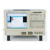
Table of Contents
Table of Contents
6
General Safety Summary
8
Service Safety Summary
10
Environmental Considerations
11
Preface
12
TLA5000 Series Logic Analyzers
12
Documentation
12
Figure I: TLA5000 Series Logic Analyzer
12
Table I: Related Documentation
13
Basic Installation
14
Check the Shipping List
14
Environmental Considerations
14
Chassis Ground Connections
14
Connecting Accessories
15
Figure 1: Location of the Ground Connection
15
Figure 2: Accessory Connections
16
Connecting Probes
17
Table 1: Accessory Connection Information
17
First Time Operation
18
Figure 3: Connecting the P64Xx Logic Analyzer Probes
18
Figure 4: Power Cord Connector Location
19
Performing the Incoming Inspection
20
Backing up User Files
20
Connecting Probes to the Target System
20
Additional Information
21
Product Overview
22
Front Panel Controls
22
External Connectors
22
Figure 5: Logic Analyzer Front Panel
22
Restoring and Installing Software
24
Restoring the Hard Disk Image
24
Reinstalling the Hard Disk Image
24
Table 2: TLA User File Suffixes
25
Table 3: BIOS Boot Settings for Reinstalling Software from the CD-ROM
26
Installing the TLA Application Software
27
Upgrading or Restoring Firmware
29
Appendix A: User Service Procedures
30
General Care
30
Self Calibration
30
Preventive Maintenance
30
In Case of Problems
32
Table 4: Failure Symptoms and Possible Causes
34
Repacking for Shipment
35
Appendix B: Accessories and Options
36
Standard Accessories
36
Optional Accessories
36
Options
37
Index
38
Advertisement
Related Products
Tektronix TLA500 Series
Tektronix TLA5204
Tektronix TLA5201
Tektronix TLA5000B Series
Tektronix TLA5201B
Tektronix TLA5202B
Tektronix TLA5204B
Tektronix TLA5203B
Tektronix TLA5202
Tektronix TLA622
Tektronix Categories
Test Equipment
Measuring Instruments
Amplifier
Portable Generator
Printer
More Tektronix Manuals
Login
Sign In
OR
Sign in with Facebook
Sign in with Google
Upload manual
Upload from disk
Upload from URL