Sign In
Upload
Manuals
Brands
Tektronix Manuals
Measuring Instruments
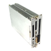
TLA 7QS
Tektronix TLA 7QS Logic Analyzer Manuals
Manuals and User Guides for Tektronix TLA 7QS Logic Analyzer. We have
1
Tektronix TLA 7QS Logic Analyzer manual available for free PDF download: Technical Reference Manual
Tektronix TLA 7QS Technical Reference Manual (139 pages)
Training Board
Brand:
Tektronix
| Category:
Measuring Instruments
| Size: 2 MB
Table of Contents
Table of Contents
3
General Safety Summary
9
Service Safety Summary
11
Preface
12
How to Use this Document
12
Related Documentation
13
Manual Conventions
13
Contacting Tektronix
13
Getting Started
14
Product Description
14
Accessories
14
Configuration
14
Functional Check
15
Hardware Features
16
Circuit Board Modules
16
Microprocessor Module
16
Table 2-1: Microprocessor Chip Select Lines
16
Table 2-2: PORTA Signals
17
Signal Sources Module
19
User Interface Module
20
Input and Output Connectors
21
Serial Port Requirements
21
Table 2-3: RS-232 Connector Pinouts
22
Software Features
23
Operating Modes
23
Stand-Alone Mode
23
Host-Controlled Mode
23
Debug Mode
24
Main Software Routine
24
Embedded Programs
24
Lites
25
Stop Lites
25
Strings
25
Counter
25
Pattern Gen
25
Show Cycles
25
Wait State
26
Int Latency
26
Pgm Delay
26
Auto Delay
26
Pulse
26
Setup/Hold
27
Pgm Flash
27
Laport Enable
27
Trig Enable
28
Diags
28
Monitor
28
Interrupt Service Routines
28
LCD User Interface
29
UP and DN Buttons
29
RUN Button
29
STOP Button
29
RS-232 Interface
29
Diagnostics
30
LCD Test
30
Serial Port Tests
30
ROM Test
31
RAM Test
31
Memory Maps
32
Memory Mapped Input and Output
32
LCD Display
32
LED Displays
32
Table 2-4: Input and Output Device Addresses
32
Input Control Bits Register
33
Table 2-5: Input Control Bits
33
Output Control Bits Register
34
Programmable Delay Setup and Hold Violation Circuit
34
Read-Write Setup and Hold Violation Memory
34
Table 2-6: Output Control Bits
34
Low Counter Pattern Generator Data
35
High Counter Pattern Generator Data
35
Memory Maps
35
Creating Programs for the Training Board
41
Preparation
41
Software Development Systems Tools
41
Tektronix Software Tools
41
Writing the Program
42
Create the Menu Entry
42
Include the User Header File
42
Create a Dummy Function
42
Write the Code
43
Compiling and Linking Code
43
Compile the Code
43
Link the Code
43
Writing an Image to the Flash Memory
44
Running the Program
44
Specifications
45
Table 3-1: Microprocessor Signal Characteristics
45
Table 3-2: Signal Source Characteristics
47
Table 3-3: Hardware Characteristics
48
Table 3-4: Power Distribution Characteristics
49
Table 3-5: Mechanical Characteristics
50
Theory of Operation
51
Circuit Board Modules
51
Microprocessor Module
51
Signal Sources Module
52
Table 4-1: Output Control Bits
52
Table 4-2: Pattern Generator Clock Select Truth Table
54
Table 4-3: Sigclk2 Selections
54
Table 4-4: Counter-Pattern Generator Addresses
54
Table 4-5: LOCNTRSEL Bit Operation
56
Table 4-6: PATCLKSEL0 and PATCLKSEL1 Bit Operation
56
User Interface Module
58
Power Supply Module
58
Input and Output Connectors
59
Serial Ports
61
Table 4-7: Serial Port B Pinout (J500)
61
Table 4-8: Serial Port a Pinout (J600)
61
Table 4-9: Logic Analyzer Control Port Signals (J400)
62
External Trigger BNC Connectors
63
Background Debug Mode Connector
63
Table 4-10: BDM Mode Connector(J200)
63
JTAG Port
64
Power Input Connectors
64
Bus Interface Connector
64
Table 4-11: JTAG Port (J601)
64
Table 4-12: Bus Interface Connector (J180)
65
Probe Interfaces
66
Functional Verification
67
Equipment Required
67
Table 5-1: Test Equipment
67
Microprocessor Circuitry Check
68
Counter-Pattern Generator Circuitry Check
68
Digital and Analog Circuitry Check
70
Runt Pulse and Missing Pulse Check
71
Narrow Pulse Check
71
Burst Pulse Check
72
Fast Edge Signal Check
72
Metastable Glitch Signal Check
73
Staircase Signal Check
74
Maintenance
75
Preventing ESD
75
Service Strategy
75
Warranty Repair Service
75
Repair or Calibration Service
76
Self Service
76
Inspection and Cleaning
76
Troubleshooting Procedures
77
Diagnostics
77
Signal Tracing
77
Repackaging Instructions
77
Replaceable Parts
79
Parts Ordering Information
79
Using the Replaceable Electrical Parts List
79
Abbreviations
80
Component Number
80
List of Assemblies
80
Chassis Parts
80
Mfr. Code to Manufacturer Cross Index
80
Diagrams and Circuit Board Illustrations
96
Symbols
96
Component Values
96
Graphic Items and Special Symbols Used in this Manual
96
Component Locator Diagrams
96
Parts Ordering Information
129
Using the Replaceable Mechanical Parts List
129
Abbreviations
130
Chassis Parts
130
Mfr. Code to Manufacturer Cross Index
130
Appendix A: Source Code
135
System Source Code Files
135
Table A-1: TLA 7QS System Software Files
135
Sample Programs
136
User.C
136
Build.bat
137
Combine.spc
138
Advertisement
Advertisement
Related Products
Tektronix TLA7Q Series
Tektronix TLA7P4
Tektronix TLA7D2
Tektronix TLA7E1
Tektronix TLA715 Series
Tektronix TLA 7F1
Tektronix TLA 700 Series
Tektronix TLA 7L1
Tektronix TLA 7M2
Tektronix TLA 7M4
Tektronix Categories
Test Equipment
Measuring Instruments
Amplifier
Portable Generator
Printer
More Tektronix Manuals
Login
Sign In
OR
Sign in with Facebook
Sign in with Google
Upload manual
Upload from disk
Upload from URL