Sign In
Upload
Manuals
Brands
Tektronix Manuals
Inverter
RTX100B
Tektronix RTX100B Manuals
Manuals and User Guides for Tektronix RTX100B. We have
1
Tektronix RTX100B manual available for free PDF download: Service Manual
Tektronix RTX100B Service Manual (178 pages)
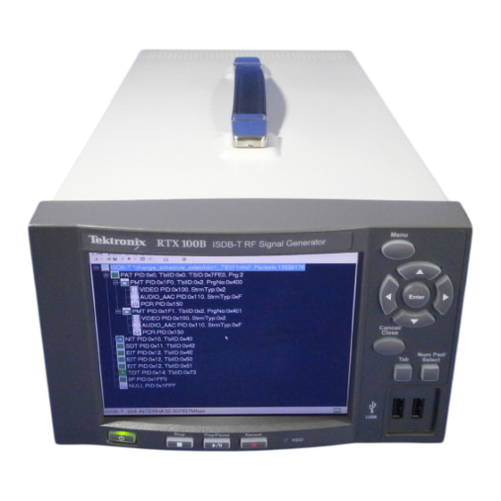
ISDB-T RF Signal Generator
Brand:
Tektronix
| Category:
Inverter
| Size: 5 MB
Table of Contents
Table of Contents
5
Environmental Considerations
15
Product Overview
23
Specifications
25
Table 1-1: Functional Specifications
26
Table 1-2: Mainframe
26
Output Level
27
Figure 1-1: Timing Diagram of the SPI Interface
33
Table 1-3: Mechanical Characteristics
34
Table 1-4: Environmental Characteristics
34
Mechanical (Physical) Characteristics
34
Table 1-5: Certifications and Compliances
35
A12 Main Board
39
A20 PCI Backplane Board
41
A150 ISDB-T RF Output Board
42
Front-Panel Processor Board
43
Figure 3-1: Pin Connections for a Crossover Ethernet Cable
47
Connecting to a Network
47
Figure 3-2: Network Connections Window
48
Figure 3-3: Local Area Connection Status Dialog Box
49
Figure 3-4: Local Area Connection Properties Dialog Box
49
Figure 3-5: Internet Protocol (TCP/IP) Properties Dialog Box
50
Table 3-1: Equipment Required for Performance Verification
52
Table 3-2: RTX100B Test Record
53
Procedures
54
Figure 3-6: Equipment Connection for Checking the Internal Clock Output Level
55
Figure 3-7: Equipment Connection for Checking the Internal Clock Frequency
56
Figure 3-8: Equipment Connection for Checking the Play Operation- SPI Interface
57
Figure 3-9: Equipment Connections for Checking the External Clock/Reference and Trigger Inputs
61
Frequency
61
Interface
62
Figure 3-10: Equipment Connection for Checking the Output Signal- ASI Interface
64
Interface
64
Figure 3-11: Equipment Connections for Checking the Play Operation- ASI Interface
66
Figure 3-12: Equipment Connection for Checking the Record Operation- ASI Interface
67
Figure 3-13: Equipment Connection for Checking the Recorded File- ASI Interface
69
Figure 3-14: Fifth Equipment Connection for Checking the ASI
70
Interface
70
Figure 3-15: Equipment Connection for Checking the Carrier Leakage
72
Table 3-3: Output Channel and Center Frequency Settings
73
Figure 3-16: Equipment Connection for Checking the Output Level and Error
75
Figure 3-17: Equipment Connection for Checking the Ieee1394B
77
Interface
77
Figure 3-18: Equipment Setup for Option Gbe Performance Verification
83
Figure 3-19: IP Playout Configuration Dialog Box
85
Figure 3-20: RTX100B MPEG Player Display with 40.000000 Mbps
86
Figure 3-21: Open Transport Stream Dialog Box
87
Figure 3-22: Selecting the IP Interface
88
Figure 3-23: Interface Settings
89
Figure 3-24: IP Flow Selection
90
Figure 3-25: MTS400 Series TS Compliance Analyzer Display
91
Figure 3-26: Clock Dialog Box
92
Figure 3-27: RTX100B MPEG Player Display with Maximum Bit Rate
93
Figure 3-28: MTS400 Series TS Compliance Analyzer Display for Maximum Bit Rate
94
Table 4-1: Equipment Required
97
Requirement for Adjustment
97
Carrier Leakage Adjustment
98
Table 4-2: Output Channel and Center Frequency Settings
99
Related Maintenance Procedures
103
Preparation
104
Inspection and Cleaning
105
Table 5-1: External Inspection Check List
106
Table 5-2: Internal Inspection Check List
107
Removal and Installation Procedures
109
Table 5-3: Summary of Procedures
110
Table 5-4: Tools Required for Module Removal
111
Figure 5-1: RTX100B Orientation
112
Figure 5-2: External Modules
113
Figure 5-3: Board Modules
114
Figure 5-4: Internal Modules
115
Access Procedure
116
Procedures for External Modules
117
Figure 5-6: Cabinet Removal
118
Figure 5-7: Right-Side and Left-Side Covers Removal
119
Figure 5-8: Front-Panel Unit Removal
120
Figure 5-9: Disassembly of Front-Panel Assembly
122
Procedure for Board Modules
123
Figure 5-10: A150 RF Output Board, A12 Main Board CPU Board, and A20 PCI Backplane Board Removal
124
Procedure for Internal Modules
128
Figure 5-11: Hard Disk Drive Removal
129
Verification
130
Figure 5-12: Internal and External Fan Removal
131
Figure 5-13: 12 V Main Power Supply and A40 AC Distributor Board Removal
133
Figure 5-14: RFI Filter Removal
134
Verifying the BIOS Configuration
135
Troubleshooting
137
Figure 5-15: Troubleshooting Procedure (1)
138
Figure 5-16: Troubleshooting Procedure (2)
139
Figure 5-17: Troubleshooting Procedure (3)
140
Figure 5-18: Troubleshooting Procedure (4)
141
Figure 5-19: Troubleshooting Procedure (5)
142
Figure 5-20: Troubleshooting Procedure (6)
143
Figure 5-21: Troubleshooting Procedure (7)
144
Figure 5-22: Troubleshooting Procedure (8)
145
Figure 5-24: A20 PCI Backplane Board View- -Right Side
146
System Software Recovery
147
Using the Rescue Disk
149
Parts Ordering Information
165
Using the Replaceable Parts List
167
Figure 8-1: Cabinet and Covers
169
Figure 8-2: Internal Modules (1)
171
Figure 8-3: Internal Modules (2)
173
Figure 8-4: Front Panel Unit
175
Figure 8-5: Cables
177
Advertisement
Advertisement
Related Products
Tektronix RTX100A
Tektronix RG 501
Tektronix RTX130B
Tektronix RTX130A
Tektronix RTM 506
Tektronix RTPA2A
Tektronix RTD 710A
Tektronix R7CO3
Tektronix RMD3000 Series
Tektronix RSA600 Series
Tektronix Categories
Test Equipment
Measuring Instruments
Amplifier
Portable Generator
Printer
More Tektronix Manuals
Login
Sign In
OR
Sign in with Facebook
Sign in with Google
Upload manual
Upload from disk
Upload from URL