Sign In
Upload
Manuals
Brands
Tektronix Manuals
Media Converter
PSC1125
Tektronix PSC1125 Manuals
Manuals and User Guides for Tektronix PSC1125. We have
1
Tektronix PSC1125 manual available for free PDF download: Instruction Manual
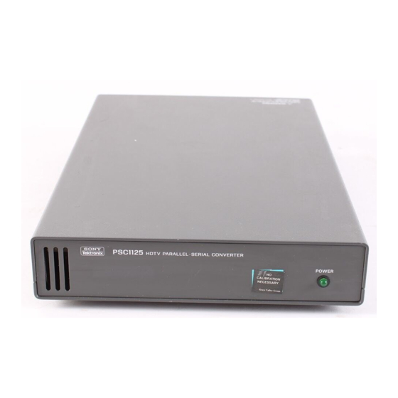
Tektronix PSC1125 Instruction Manual (92 pages)
Digital Television Parallel-to-Serial Converter
Brand:
Tektronix
| Category:
Media Converter
| Size: 0 MB
Table of Contents
Table of Contents
7
Figure 1-1: Block Diagram
15
Product Description
15
Table 1-1: Standard Accessories
16
Options and Accessories
16
Installation
17
Signal
18
Table 1-2: Files on the TSG1001 Signal Library Floppy Disk
18
Figure 2-1: PSC 1125 Front Panel
21
Front Panel Overview
21
Figure 2-2: PSC 1125 Rear Panel
22
Rear Panel Overview
22
Customer Maintenance
23
Table 3-1: Digital Video Interface
25
Table 3-2: Embedded Audio
26
Figure 3-1: Parallel Input Connector (Y, PB/PR)
26
Figure 3-2: Data-To-Clock Relation (Parallel Input)
27
Table 3-3: AC Power Source
27
Table 3-4: Installation Requirements
27
Table 3-5: Environmental Characteristics
27
Table 3-7: Physical Characteristics
30
Before Running the Tests
33
Table 4-1: Required Equipment
33
Performance Tests
34
Table 4-2: Files on the TSG1001 Signal Library Floppy Disk
34
Figure 4-1: Performance Check Initial Hookup
37
Figure 4-2: Eye Pattern Test Initial Hookup
40
Figure 4-3: Example of Eye Pattern for an Acceptable Output Signal
42
Removing the Top Cover and Shield Cover
45
(J300149 - J310100)
46
Figure 5-2: Jumper Configuration for Selecting Sound Packets
46
(J310101 and Above)
47
Figure 5-3: Jumper Configuration for Selecting Sound Packets
47
Figure 5-1: Location of J400
45
Requirements for Performance
49
Table 6-1: Test Equipment
49
Voltage Adjustment
50
Figure 6-1: A10 Board View and Test Points
50
Figure 6-2: Power Supply Board View and VR1
50
Table 6-2: Test Points and Voltage Ranges
51
Tektronix Service Offerings
53
Preparation
54
Table 7-1: Relative Susceptibility to Static-Discharge Damage
55
Inspection and Cleaning
56
Table 7-2: External Inspection Check List
57
Table 7-3: Internal Inspection Check List
57
Removal and Installation Procedures
60
Table 7-4: Equipment Required
60
Figure 7-1: Top Cover and Shield Cover Removal
62
Figure 7-2: Removal of Power Indicator Module Holder Attachment
63
Figure 7-3: Removal of Power Indicator Module LED and Holder
63
Figure 7-4: Power Indicator Assembly Interconnect Cable Removal
64
Figure 7-5: Noise Filter and Power Supply Module Removal
65
Figure 7-6: Fan Module Removal
66
Figure 7-7: A10 Module Removal
68
Figure 7-8: Input and Output Connector Removal
69
Figure 7-9: Front Panel and Bottom Cover Removal
70
Repackaging
71
Troubleshooting
72
Parts Ordering Information
75
Figure 8-1: Main Chassis and Circuit Boards
79
Figure 8-2: Front Panel and Power Indicator
81
Figure 8-3: Rear Panel and Grounding
83
Figure 9-1: Interconnections
85
Figure 9-2: Block Diagram
86
Advertisement
Advertisement
Related Products
Tektronix P6701B
Tektronix P6703B
Tektronix P6723
Tektronix P6701A
Tektronix P6703A
Tektronix P6711
Tektronix P6713
Tektronix P6701
Tektronix PS 501-2
Tektronix PSM4120
Tektronix Categories
Test Equipment
Measuring Instruments
Amplifier
Portable Generator
Printer
More Tektronix Manuals
Login
Sign In
OR
Sign in with Facebook
Sign in with Google
Upload manual
Upload from disk
Upload from URL