Sign In
Upload
Manuals
Brands
Tektronix Manuals
Inverter
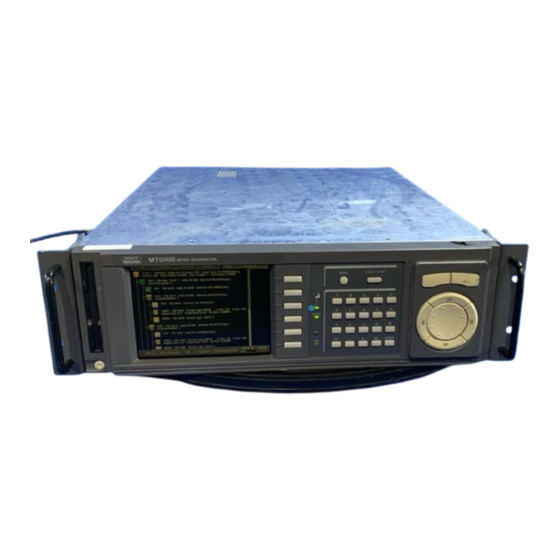
MTG100, MTG300
Tektronix MTG100, MTG300 Manuals
Manuals and User Guides for Tektronix MTG100, MTG300. We have
1
Tektronix MTG100, MTG300 manual available for free PDF download: Service Manual
Tektronix MTG100, MTG300 Service Manual (188 pages)
MPEG Generator
Brand:
Tektronix
| Category:
Inverter
| Size: 3 MB
Table of Contents
Warranty
3
Table of Contents
5
General Safety Summary
11
Service Safety Summary
13
Electrical Parts List
15
Diagrams
15
Manual Structure
15
Manual Conventions
16
Finding Other Information
16
Contacting Tektronix
17
Performance Check Interval
19
Strategy for Servicing
19
Tektronix Service Offerings
20
Product Overview
21
Table 1-1: Main Product Features
21
General Characteristics
23
Specifications
23
Table 1-2: Functional Characteristics
24
Table 1-3: Electrical Characteristics
26
Table 1-4: Mechanical Characteristics
29
Table 1-5: Environmental Characteristics
30
Table 1-6: Certifications and Compliances
31
Supplying Operating Power
33
Installation
33
Table 2-1: Power-Cord Conductor Identification
34
Table 2-2: Power Cord Identification
34
Operating Environment
35
Ventilation Requirements
35
Applying and Interrupting Power
36
Figure 2-1: Rear Panel Power Connector and Power Switch
36
Figure 2-2: Front Panel Power Switch
37
Repackaging Instructions
38
Installed Options
38
Operating Instructions
39
Using the Menu System
39
Figure 2-3: Elements of the Menu System
39
Figure 2-4: Front Panel Showing the Pull-Down Menu Controls
40
Figure 2-5: Example of a Displayed Pull-Down Menu
41
Figure 2-6: Display States of the Pull-Down Menu Commands
41
Figure 2-7: Front Panel Showing the Bezel Menu Controls
42
Table 2-3: Display States of the Bezel Menu Commands
42
Figure 2-8: Hexadecimal Keypad
43
Figure 2-9: Dialog Box Showing Knob Icon and Underscore Character
44
Figure 2-10: Dialog Box for Text Input
44
Output Loop Modes
45
Figure 2-11: Pop-Up Message Box
45
Theory of Operation
47
A10 Main Board
47
CPU Unit
48
A40 MISC (Power Distribution & Interface) Board
49
A50 SCSI Termination Boards
49
A30 Front Panel Board
49
A35 Power Switch
49
Power Supply
49
Equipment and Test Signals Required
51
Table 4-1: Equipment Required for Performance Verification
51
Figure 4-1: Custom Cable with 9-Pin and 25-Pin, D-Type Connectors
52
Table 4-2: MPEG Test Files Required for Performance Verification
52
Procedures
53
Figure 4 2: Equipment Connection for Verifying the Internal Clock Frequency
54
Figure 4-3: Initial Equipment Connection for Verifying the ASI Output
56
Figure 4-4: Second Equipment Connection for Verifying the ASI Output
57
Figure 4-5: Initial Equipment Connection for Verifying the SSI Output
58
Figure 4-6: Second Equipment Connections for Verifying the SSI Output
59
Parallel Output
60
Figure 4-7: Equipment Connection for Verifying the Parallel Output
61
Figure 4-8: Equipment Connection for Verifying the Serial Output
62
Figure 4-9: Equipment Connections for Verifying the External Clock Input
64
Frequency
65
Figure 4-10: Equipment Connections for Verifying the External Reference Input
67
Requirements for Adjustment
69
Adjustment Procedures
69
Table 5-1: Equipment Required
69
Clock Frequency Adjustment
70
Figure 5-1: A10 Main Board View
70
Related Maintenance Procedures
73
Maintenance
73
Preparation
74
Table 6-1: Relative Susceptibility to Static-Discharge Damage
75
Inspection and Cleaning
76
Table 6-2: External Inspection Check List
77
Table 6-3: Internal Inspection Check List
78
Removal and Installation Procedures
81
Preparation
81
General Instructions
82
Table 6-4: Summary of Procedures
82
Table 6-5: Tools Required for Module Removal
83
Figure 6-1: MPEG Generator Orientation
84
Figure 6-2: External Modules
85
Figure 6-3: Internal Modules
86
Figure 6-4: Board Modules and CPU Unit
87
Figure 6-5: Rear Panel Modules
88
Access Procedure
89
Figure 6-6: Guide to Removal Procedures
89
Procedures for External Modules
90
Figure 6-7: Cabinet Removal
92
Figure 6-8: Front-Panel Unit Removal
94
Figure 6-9: Disassembly of Front-Panel Assembly
96
Procedure for Internal Modules
97
Figure 6-10: Fan Removal
98
Figure 6-11: Floppy Disk Drive Removal
99
Figure 6-13: Attaching the Data Hard Disk to the Chassis
101
Figure 6-12: Data Hard Disk Drive Removal
101
Figure 6-14: System Hard Disk Drive Removal
103
Display Module
104
Figure 6-15: Display Module Removal
105
Figure 6-16: Power Supply Unit Removal
107
Figure 6-17: 5 V Power Supply, 12 V Power Supply, Power Switch, and Inlet Removal
108
Procedure for Board Modules and CPU Unit
109
Figure 6-18: A10 Main Board Removal
110
Figure 6-19: A40 MISC (Power Distribution & Interface) Board Removal
112
Figure 6-20: CPU Unit Removal
114
Figure 6-21: CPU, A20 Interface, and LAN Boards Removal
115
Procedures for Rear Panel Modules
116
Figure 6-22: Rear Panel Modules Removal
119
Troubleshooting
121
Table 6-6: Error Messages at Power on Diagnostics
121
Service Menu
122
Table 6-7: Bezel Menu Items in the Service Menu
123
Troubleshooting Trees
125
Figure 6-23: Troubleshooting Procedure (1)
125
Figure 6-24: Troubleshooting Procedure (2)
126
Figure 6-25: Troubleshooting Procedure (3)
127
Figure 6-26: Troubleshooting Procedure (4)
128
Figure 6-27: Troubleshooting Procedure (5)
129
Figure 6-28: Troubleshooting Procedure (6)
130
Figure 6-29: Troubleshooting Procedure (7)
131
Figure 6-30: Troubleshooting Procedure (8)
132
Figure 6-31: Troubleshooting Procedure (8)
133
Figure 6-32: Troubleshooting Procedure (9)
134
Figure 6-33: Troubleshooting Procedure (10)
135
Figure 6-34: Troubleshooting Procedure (11)
136
Figure 6-35: Troubleshooting Procedure (12)
137
Figure 6-36: Location of the A40 MISC (Power Distribution Interface) Board
138
Equipment Required
139
Firmware Updates
139
Update Procedure
139
Table 6-8: Equipment Required
139
Figure 6-38: Message Box Appearing after the File Transfer Is Complete
140
Figure 6-37: MTG Series Firmware Update Dialog Box
140
Figure 6-39: Message Box Appearing after the Update Is Complete
141
Figure 6-40: Message Box Appearing after Turn on the Instrument
141
Figure 6-41: System Dialog Box
142
Replacing the Hard Disk Drive(S)
143
Data Hard Disk Drives
144
System Hard Disk Drive
146
Hardware Device Error Codes
149
Table 6-10: Hardware Device Error Codes
150
Table 6-11: Error Messages
153
Options and Accessories
157
Table 7-1: Options
157
Table 7-2: Standard Accessories
157
Table 7-3: Optional Accessories
158
Electrical Parts List
159
Parts Ordering Information
167
Mechanical Parts List
167
Using the Replaceable Parts List
168
Replaceable Parts List
170
Figure 10-1: Cabinet
171
Figure 10-2: Front Panel Unit
173
Figure 10-3: Internal Modules and Rear Connectors
175
Figure 10-4: Hard Disk Drives
177
Figure 10-5: Board Modules and Inner Units
179
Figure 10-6: CPU Unit
181
Figure 10-7: Power Supply Unit
183
Figure 10-8: Rack Mount
185
Advertisement
Advertisement
Related Products
Tektronix MTG300
Tektronix MTM400A
Tektronix MTS415
Tektronix MTS4SA MPEG
Tektronix MTS4KUP ESE
Tektronix MTS4KUP PQ
Tektronix MTS4KUP VQ
Tektronix MTS4KUP VS
Tektronix MTS4KUP IPTV
tektronix MTS4EAV7
Tektronix Categories
Test Equipment
Measuring Instruments
Amplifier
Portable Generator
Printer
More Tektronix Manuals
Login
Sign In
OR
Sign in with Facebook
Sign in with Google
Upload manual
Upload from disk
Upload from URL