Sign In
Upload
Manuals
Brands
Tektronix Manuals
Test Equipment
MSO 2 Series
Tektronix MSO 2 Series Manuals
Manuals and User Guides for Tektronix MSO 2 Series. We have
2
Tektronix MSO 2 Series manuals available for free PDF download: Help Manual, Service Manual
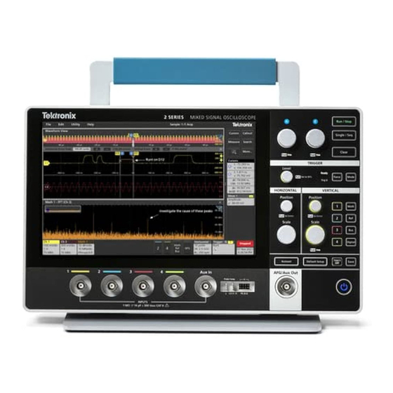
Tektronix MSO 2 Series Help Manual (275 pages)
Brand:
Tektronix
| Category:
Test Equipment
| Size: 7 MB
Table of Contents
Table of Contents
3
Tektronix End User License Agreement
11
Open Source GPL License Notice
12
Instrument Compliance Markings
13
Welcome to the 2 Series MSO Help
14
Product Documents and Support
15
Product Support and Feedback
15
Product Documentation
15
Installing Your Instrument
17
Install Option Upgrade Licenses
17
Operating Requirements
17
Input Signal Requirements
18
Check that the Instrument Passes Power-On Self Tests
18
Battery Pack Information
19
Battery Pack Installation
19
Operating Safely with Battery Power
21
Rechargeable Battery Installation
22
Rechargeable Battery Removal
23
Battery Status
23
Instrument Stand to Battery Pack Installation
25
Connecting Probes to the Instrument
26
Rackmount Option Information
26
Getting Acquainted with Your Instrument
27
Front Panel Controls and Connectors
27
Button and Knob Functions
28
Rear and Side Panel Connections
30
Instrument Stand Installation
32
User Interface
33
User Interface Elements
35
Badges
36
Moving Waveform and Measurement Badges
43
Group Signal Badges in the Settings Bar
43
Configuration Menus
44
Zoom User Interface
45
Using the Touch Screen Interface for Common Tasks
46
Accessing Application Help
48
Configure the Instrument
49
Download and Install the Latest Instrument Firmware
49
Set the Time Zone and Clock Readout Format
49
Functional Check
50
Run Signal Path Compensation (SPC)
50
Compensate the Probe
51
Connect to a Network (LAN)
52
Mount a Network Drive from a Standard Instrument
52
Mount Tekdrive
53
Unmount a Network Drive from a Standard Instrument
54
Unmount a Tekdrive
54
Connect the Oscilloscope to a PC Using a USB Cable
54
Deskew Analog Input Channels - Quick Visual Method
54
Deskew Analog Input Channels
55
Connect a Keyboard or Mouse
56
ESD Prevention Guidelines
56
Analog Channel Operating Basics
57
Acquiring a Signal
57
Autoset to Quickly Display a Waveform
57
Set Horizontal Parameters
58
How to Trigger on a Signal
59
Set the Acquisition Mode
60
Start and Stop an Acquisition
60
Add a Channel Waveform to the Display
61
Configure Channel or Waveform Settings
62
Add a Math, Reference, or Bus Waveform
62
Add a Measurement
64
Configure a Measurement
66
Delete a Measurement or Search Badge
67
Display an XY Plot
68
Display an FFT Math Waveform
68
Add a Serial Bus to the Waveform View
68
Add a Parallel Bus to the Waveform View
70
Add a Search
72
Change Waveform View Settings
73
Display and Configure Cursors
74
Using Default Setup
76
Add a Callout to a View
76
Delete a Callout
77
Acquiring Digital Signals
78
Connect and Set up Digital Signals
78
Advanced Triggering
79
Triggering Concepts
79
Trigger on a Pulse Width Event
79
Trigger on a Timeout Event
80
Trigger on a Runt Signal Event
81
Trigger on a Logic Event
82
Trigger on a Setup-Hold Event
83
Trigger on a Rise or Fall Time Event
83
Set up Trigger on a Parallel Bus
84
Set up Trigger on a Serial Bus
85
Set Trigger Holdoff
85
Trigger on an External Signal Using the aux Input
85
Setting Waveform Display Parameters
87
Set Waveform Display Mode (Stacked or Overlay)
87
Set the Waveform Interpolation Mode
87
Set the Waveform Persistence, Style, and Intensity
87
Set the Graticule Style and Intensity
88
Mask Testing Waveforms
89
Create a Mask
89
Edit Mask Segments on the Screen
89
Edit Mask Segments Using the Mask Definition Menu
92
Zoom in on Waveforms
95
Turn on Zoom Mode
95
Using Wave Inspector Front-Panel Controls for Zoom
96
Zoom Mode and Searches
96
Measurement Configuration
97
Label a Measurement
97
Set Measurement Reference Levels
97
Set Measurement Gates
98
Saving and Recalling Information
100
Save a Screen Image
100
Save a Waveform to a File
100
Save Instrument Settings to a File
101
Save Reports
101
Save Sessions
102
Recall a Reference Waveform
103
Recall a Setup File
103
Recall a Session File
104
Menus and Dialog Boxes
105
Act on Event Configuration Menu
105
Add Measurements Configuration Menu Overview
106
The Standard Measurements Tab
107
Amplitude Measurements Panel
107
Time Measurements Panel
109
The FRA Tab
111
Control Loop Response (Bode) Measurement Configuration Panel
111
Configure Profile
113
Connect to an External Signal Generator
114
Measurement Configuration Menu Overview
114
Measurement Name Panel (Measurement Configuration Menu)
115
Configure Panel (Measurement Configuration Menu)
116
Reference Levels Panel (Measurement Configuration Menu)
116
Gating Panel (Measurement Configuration Menu)
118
Pass/Fail Testing Panel (Measurement Settings Menu)
119
Add Plot Configuration Menu
120
Add Results Table Configuration Menu
120
Results Tables Operations Overview
120
Frequency Response Analysis (FRA) Results Table Configuration Menu
121
Save as Configuration Menu, Custom Results Table
121
Measurement Table Configuration Menu
122
Save as Configuration Menu (Measurement Results Table)
123
Search Results Table Menu
123
Save as Configuration Menu (Search Results Table)
125
Bus Decode Results Table Configuration Menu
125
Save as Configuration Menu (Bus Decode Results Table)
126
Bus Configuration Menu
127
Parallel Bus Configuration Menu
127
Parallel Bus - Define Inputs Menu
129
I2C Serial Bus Configuration Menu
129
SPI Serial Bus Configuration Menu
130
RS232 Serial Bus Menu
132
CAN Serial Bus Configuration Menu
133
LIN Serial Bus Configuration Menu
136
SENT Serial Bus Configuration Menu
137
Search Configuration Menu Overview
138
Bus Search Configuration Menus
139
Parallel Bus Search Configuration Menu
139
I2C Serial Bus Search Configuration Menu
140
SPI Serial Bus Search Configuration Menu
141
Serial Bus Search Configuration Menu
142
CAN Serial Bus Search Configuration Menu (When Not Using a .Dbc Symbol Definition File)
143
CAN Serial Bus Search Configuration Menu (When Using a .Dbc Symbol Definition File)
145
CAN DBC Symbolic Configuration Menu
147
LIN Serial Bus Search Configuration Menu
148
SENT Serial Bus Search Configuration Menu
149
Configure Pattern Editor
151
Edge Search Configuration Menu
151
Logic Search Configuration Menu
152
Logic Search - Define Inputs Configuration Menu
154
Pulse Width Search Configuration Menu
154
Rise/Fall Time Search Configuration Menu
156
Runt Search Configuration Menu
157
Setup and Hold Search Configuration Menu
158
Setup and Hold Search - Define Inputs Configuration Menu
159
Timeout Search Configuration Menu
160
Analog Channel Configuration Menu
161
Invert Channel Guidelines
162
AFG Configuration Menu
163
Cursor Configuration Menu
165
Date and Time Configuration Menu
166
Digital Channel Configuration Menu
167
Horizontal Configuration Menu
167
Acquisition Configuration Menu
169
More (DRAW a BOX Menu)
169
Mask Badge Configuration Menu
170
Mask Definition Configuration Menu
170
Right Click Menu Functions Associated with Mask Segments
173
Mask Test Badge Configuration Menu
174
Right Click Menu Functions Associated with the Mask Test Badge
175
Math Configuration Menu Overview
175
Math Configuration Menu
175
Equation Editor (Math Configuration Menu)
177
Add Functions (Math Equation Editor)
178
Menu Bar Overview
179
Recall Configuration Menu (File Menu)
180
Save as Configuration Menu (File Menu)
181
Browse Save as Location Configuration Menu
184
File Utilities Configuration (File Menu)
185
Mount Drive Configuration Menu
186
Undo, Redo (Edit Menu)
188
User Preferences (Utility Menu)
188
Connected Oscilloscope Preferences
191
Legalese
191
Define Custom Colors Menu
192
I/O (Utility Menu)
193
LAN Reset Configuration Menu (Utility > I/O Menu)
195
Self Test Configuration Menu (Utility Menu)
196
Calibration Configuration Menu (Utility Menu)
196
Security Configuration Menu
197
Teksecure Erase Memory
198
Enter Password Configuration Menu
198
Set Password Configuration Menu
199
Change Password Configuration Menu
200
Demo (Utility Menu)
200
Help
201
License Options
201
About (Help Menu)
201
Location to Save Exit Key Configuration Menu
202
Browse License Files Menu (Help > About)
203
Font Color Menu (Text Settings Configuration)
204
Text Settings Configuration Menu (Callout and Waveform Labels Text)
204
Pattern Generator Configuration Menu
205
Plot Configuration Menus
206
Plot XY Configuration Menu
206
Save as Configuration Menu (Plot Save Panel, Save Plot Image Button)
207
Save as Configuration Menu (Plot Save Panel, Save Plot Data Button)
207
Control Loop Response (Bode) Plot Configuration Menu
208
Reference Waveform Configuration Menu
209
Recall Configuration Menu (Ref Waveform Configuration Menu)
210
Search Configuration Menu
211
Trigger Configuration Menu Overview
212
Edge Trigger Configuration Menu
212
Pulse Width Trigger Configuration Menu
214
Timeout Trigger Configuration Menu
215
Runt Trigger Configuration Menu
215
Logic Trigger Configuration Menu
216
Logic Trigger - Define Inputs Configuration Menu
217
Setup and Hold Trigger Configuration Menu
218
Setup and Hold Trigger - Define Inputs Configuration Menu
219
Rise/Fall Time Trigger Configuration Menu
219
Bus Trigger Configuration
220
CAN Serial Bus Trigger Settings Panel
220
I2C Serial Bus Trigger Settings Panel
222
LIN Serial Bus Trigger Settings Panel
224
Parallel Serial Bus Trigger Settings Panel
225
RS-232 Serial Bus Trigger Settings Panel
226
SENT Serial Bus Trigger Settings Panel
227
SPI Serial Bus Trigger Settings Panel
229
Virtual Keyboard
230
Bus Trigger Radix-Specific Virtual Keypads
230
Virtual Keypad
231
Waveform View Configuration Menu
231
Waveform Acquisition
233
Acquisition Concepts
233
Acquisition Hardware
233
Sampling Process
233
Real-Time Sampling
233
Interpolated Real-Time Sampling
233
Waveform Record
233
Interpolation
234
Acquisition Modes
234
Waveform Sample Interpolation
235
Coupling
235
Scaling and Positioning
235
Vertical Acquisition Considerations
236
Horizontal Acquisition Considerations
236
Triggering Concepts
237
Trigger Sources
237
Trigger Types
238
Trigger Modes
238
Trigger Holdoff
238
Trigger Coupling
239
Trigger Slope and Level
239
Trigger Position in Waveform Record
239
Advanced Triggering
240
Bus Triggering Concepts
240
Pulse Width Trigger Concepts
240
Timeout Trigger Concepts
240
Runt Trigger Concepts
240
Logic Trigger Concepts
241
Setup and Hold Trigger Concepts
241
Rise/Fall Time Trigger Concepts
241
Waveform Display Concepts
242
Waveform Preview Mode
242
Horizontal Position and the Horizontal Reference Point
242
Measurement Concepts
243
Measurement Variables
243
Missing or Out-Of-Range Samples
245
Math Waveforms
245
Math Waveform Elements
246
Math Waveform Sources
247
Guidelines for Working with Math Waveforms
247
Math Waveform Editor Syntax
247
Math Waveform Differentiation
248
Math Waveform Offset, Position, and Scale
249
Waveform Integration
249
FFT Process
250
FFT and Aliasing
250
Blackman-Harris FFT Window Concepts
251
Flattop2 Window
252
Gaussian Window
252
Hanning FFT Window
253
Hamming Window
253
Kaiser-Bessel FFT Window
254
Rectangular Window
254
Tek-Exponential Window
255
Measurement Algorithms
256
Amplitude Measurement Algorithms
256
AC RMS Measurement Algorithm
256
Area Measurement Algorithm
256
Amplitude Measurement Algorithm
256
Base Measurement Algorithm
256
Integration Algorithm
256
Maximum Measurement Algorithm
257
Mean Measurement Algorithm
257
Minimum Measurement Algorithm
257
Negative Overshoot Measurement Algorithm
257
Positive Overshoot Measurement Algorithm
258
Peak-To-Peak Measurement Algorithm
258
RMS Measurement Algorithm
258
Top Measurement Algorithm
258
Time Measurement Algorithms
258
Burst Width Measurement Algorithm
258
Data Rate Measurement Algorithm
258
Delay Measurement Algorithm
258
Falling Slew Rate
258
Fall Time Measurement Algorithm
259
Frequency Measurement Algorithm
260
High Time Measurement Algorithm
260
Hold Time Measurement Algorithm
260
Low Time Measurement Algorithm
260
N-Periods Duration Measurement Algorithm
261
Negative Duty Cycle Measurement Algorithm
261
Negative Pulse Width Measurement Algorithm
261
Period Measurement Algorithm
262
Phase Measurement Algorithm
262
Positive Duty Cycle Measurement Algorithm
262
Positive Pulse Width Measurement Algorithm
262
Rising Slew Rate Measurement Algorithm
262
Rise Time Measurement Algorithm
263
Setup
263
Skew
264
Time Outside Level Measurement Algorithm
264
Time to Max
265
Time to Min
265
Unit Interval Measurement Algorithm
265
Frequency Response Analysis Algorithms
265
Control Loop Response (Bode) Measurement Algorithm
265
Index
266
Advertisement
Tektronix MSO 2 Series Service Manual (25 pages)
Brand:
Tektronix
| Category:
Test Equipment
| Size: 2 MB
Table of Contents
Table of Contents
3
Important Safety Information
4
General Safety Summary
4
Service Safety Summary
4
To Avoid Fire or Personal Injury
5
Power Disconnect
5
Avoid Exposed Circuitry
5
Probes and Test Leads
6
Terms in this Manual and on the Product
7
Symbols on the Product
8
Operating Safely with Battery Power
9
Preface
10
Supported Products
10
Where to Find Operating Information
10
Theory of Operation
11
Power Supply
11
Main Board
11
Front Panel and Display
12
Maintenance
13
Preventing ESD
13
Inspection and Cleaning
13
Exterior Cleaning (Other than Display)
13
Flat Panel Display Cleaning
14
Remove and Replace Procedures
14
Required Equipment
15
Remove Front Panel Knobs
15
Disassemble Instrument
15
Troubleshooting
17
Service Level
17
Check for Common Problems
17
Troubleshooting Procedures
19
Primary Troubleshooting Procedure
19
Power Supply Troubleshooting Procedure
20
Instrument Self Tests
22
Adjustment Procedures and Interval
22
Adjustment after Repair
22
Replaceable Parts
23
Returning Instrument for Service
23
Full Assembly Parts List
23
Advertisement
Related Products
Tektronix MSO2000 Series
Tektronix MSO2012
Tektronix MSO20x4
Tektronix MSO2024B
Tektronix MSO2024
Tektronix MSO2022B
Tektronix MSO2014/B: MSO2022B
Tektronix MSO2014
Tektronix MSO2012B
Tektronix MSO2004B
Tektronix Categories
Test Equipment
Measuring Instruments
Amplifier
Portable Generator
Printer
More Tektronix Manuals
Login
Sign In
OR
Sign in with Facebook
Sign in with Google
Upload manual
Upload from disk
Upload from URL