Sign In
Upload
Manuals
Brands
Tektronix Manuals
Test Equipment
DPO75902SX
Tektronix DPO75902SX Oscilloscope Manuals
Manuals and User Guides for Tektronix DPO75902SX Oscilloscope. We have
3
Tektronix DPO75902SX Oscilloscope manuals available for free PDF download: User Manual, Quick Start User Manual, Installation And Safety Manual
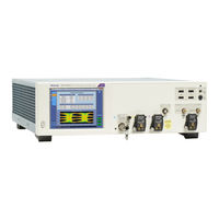
Tektronix DPO75902SX User Manual (230 pages)
Brand:
Tektronix
| Category:
Test Equipment
| Size: 17 MB
Table of Contents
Table of Contents
5
Important Safety Information
11
General Safety Summary
11
Service Safety Summary
13
Terms in the Manual
13
Terms on the Product
13
Symbols on the Product
13
Compliance Information
15
EMC Compliance
15
Safety Compliance
16
Environmental Compliance
17
Preface
19
Install Your Instrument
21
Standard Accessories
21
Operating Requirements
22
Power Supply Requirements
23
Preventing Instrument Damage
23
Preventing ESD
23
Observe Maximum Input Voltage
25
Selecting the Proper Attenuator
25
Connector Cleaning
25
Proper Connection Technique
26
Power on the Instrument
29
Power off the Instrument
30
Multi-Instrument Configuration
30
Instrument Stacking
30
Before Startup
33
Ultrasync ™ Bus Cable
33
Ultrasync ™ Bus Cable Connection Order
33
Master and Extension Connection Order
35
Multi-Instrument Power on
36
Switching between Multi-Instrument Modes
40
ATI Versus Tekconnect Channels
41
Multi-Instrument Status Displays
42
Available Features
42
DPO7AFP Auxiliary Front Panel (Optional)
43
Inspect the Instrument
43
Verify Internal Diagnostics Pass
43
Activating Windows 10
44
Windows Interface Guidelines
45
Signal Path Compensation
46
Connecting to a Network
49
Adding a Second Monitor
50
Activating Windows 10
50
Restoring Instrument Operating System and Product Software
51
Operating System Restore
51
Internal Recovery Utility
51
Product Software Installation
52
Getting Acquainted with Your Instrument
53
Front-Panel Connectors
53
Rear-Panel Connectors
55
Interface and Display
56
Control Panel
58
Accessing Online Help
59
Accessing Menus and Control Windows
60
Inspect Your Instrument
61
Verify Internal Diagnostics Pass
61
Acquisition
63
Signal Path Compensation
63
Setting up Analog Signal Input
66
Using Default Setup
68
Using Autoset
69
Probe Compensation and Deskew
70
Deskew Tool
70
Acquisition Concepts
75
Acquisition Hardware
75
Sampling Process
76
Real-Time Sampling
76
Interpolated Real-Time Sampling
76
Equivalent-Time Sampling
76
Waveform Record
77
Interpolation
77
How the Acquisition Modes Work
77
Enable Enhanced Effective Number of Bits
78
Changing the Acquisition Mode
79
Starting and Stopping an Acquisition
80
Selecting the Horizontal Mode
81
Using Fastacq
83
Using DSP Enhanced Bandwidth
84
Setting the Termination Voltage
86
Using Roll Mode
87
Setting up a Bus
88
Set up a Serial Bus
90
Set up a Parallel Bus
91
Set up Bus Display
93
Using Fastframe Mode
94
Using Fastframe Frame Finder
96
Pinpoint Triggers
99
Triggering Concepts
99
Trigger Event
99
Trigger Modes
99
Trigger Holdoff
99
Trigger Coupling
100
Horizontal Position
100
Slope and Level
100
Delayed Trigger System
100
Choosing a Trigger Type
101
Trigger Selections
103
Checking Trigger Status
104
Using a (Main) and B (Delayed) Triggers
105
Trigger on B Event
106
B Trigger after Delay Time
106
B Triggers after Arm on a
106
Arm-On-A then Trigger-On-B (Horizontal Delay On)
107
Vertical Setup Control Window (M Chx Tab)
108
Triggering with Reset
109
Correcting Trigger Position
110
Triggering with B-Event Scan
111
Triggering on a Parallel Bus
114
Triggering on a Serial Bus
116
Triggering Using Visual Triggers (Visual Triggering)
118
Setting up Action on Event
120
Sending E-Mail on Trigger
121
Setting up E-Mail on Event
122
Using Horizontal Delay
124
Display a Waveform
125
Setting the Display Style
125
Setting the Display Persistence
126
Setting the Display Format
127
Selecting the Waveform Interpolation
128
Adding Screen Text
129
Setting the Graticule Style
130
Setting the Trigger Level Marker
131
Displaying the Date and Time
131
Using the Color Palettes
132
Setting Reference Waveform Colors
133
Setting Math Waveform Colors
134
Using Multiview Zoom
135
Zooming in Multiple Areas
136
Lock and Scroll Zoomed Waveforms
138
Hide Waveforms in the Zoomed Window
139
Searching and Marking Waveforms
139
To Manually Set and Clear (Delete) Marks
140
To Automatically Set and Clear (Delete) Search Marks
142
Using a Visual Search
147
Analyzing Waveforms
149
Taking Automatic Measurements
149
Automated Measurement Selections
150
Customizing an Automatic Measurement
153
Gating
154
Statistics
154
Snapshot
155
Annotate Measurements
155
Reference Levels
156
Taking Cursor Measurements
158
Setting up a Histogram
160
Using Math Waveforms
162
Using Spectral Analysis
165
Using the Error Detector
168
Using Mask Testing
172
Using Limit Testing
175
Myscope
177
Creating a New Myscope Control Window
177
Using Myscope Control Windows
181
Saving and Recalling Information
183
Saving Screen Captures
183
Saving Waveforms
185
Recalling Waveforms
187
Saving Instrument Setups
188
Recalling Instrument Setups
189
Saving Measurements
190
Saving User Masks
191
Saving Histogram Data
192
Saving Timestamps
193
Copying Your Results to the Clipboard
194
Printing a Hard Copy
196
Run Application Software
197
Application Examples
199
Capturing Intermittent Anomalies
199
Using the Extended Desktop and Openchoice Architecture for Efficient Documentation
202
Triggering on Buses
204
Specifications
207
Vertical System Analog Channels
207
Horizontal and Acquisition System
211
Trigger Specifications
212
Input-Output Port Specifications
214
Power Source Specification
214
Mechanical Specifications
215
Environmental Specifications
215
Appendix A, Maintenance
217
Maintenance
217
Cleaning
217
Exterior Cleaning
217
Adjustment Interval
218
Adjustment
218
Flat Panel Display Cleaning
218
Returning the Instrument for Service
219
Tekscope Recovery Report Utility
219
Replaceable Parts
221
Parts Ordering Information
222
Appendix B, Version Releases
223
Obtaining the Latest Advanced Analysis Application and Version Releases
223
Advertisement
Tektronix DPO75902SX Quick Start User Manual (192 pages)
Oscilloscopes
Brand:
Tektronix
| Category:
Test Equipment
| Size: 18 MB
Table of Contents
Table of Contents
5
List of Figures
9
List of Tables
10
Important Safety Information
11
General Safety Summary
11
Service Safety Summary
13
Terms in the Manual
13
Terms on the Product
13
Symbols on the Product
13
Compliance Information
14
EMC Compliance
14
Safety Compliance
14
Environmental Compliance
16
Product End-Of-Life Handling
16
Preface
17
Conventions Used in this Manual
18
Install Your Instrument
19
Standard Accessories
19
Operating Requirements
20
Power Supply Requirements
20
Preventing Instrument Damage
21
Preventing ESD
21
Observe Maximum Input Voltage
22
Selecting the Proper Attenuator
22
Connector Cleaning
22
Table 1: Maximum ATI Voltage Range
22
Proper Connection Technique
23
Figure 1: Wear an Antistatic Wrist Strap
24
Figure 2: Installing a Connector Saver
24
Power on the Instrument
25
Figure 3: Installing a Cable
25
Figure 4: Use a Second Backing Wrench
25
Power off the Instrument
26
Multi-Instrument Configuration
27
Instrument Stacking
27
Before Startup
30
Ultrasync™ Bus Cable
30
Ultrasync™ Bus Cable Connection Order
30
Master and Extension Connection Order
31
Multi-Instrument Power on
32
Switching between Multi-Instrument Modes
36
ATI Versus Tekconnect Channels
37
Multi-Instrument Status Displays
37
Available Features
38
Table 2: Stand-Alone Instrument
38
Table 3: Multi-Unit Configuration
38
DPO7AFP Auxiliary Front Panel (Optional)
39
Inspect the Instrument
40
About this Task
40
Verify Internal Diagnostics Pass
40
Activating Windows 10
41
First Time Activation
41
Windows Interface Guidelines
42
Signal Path Compensation
42
Connecting to a Network
44
Adding a Second Monitor
44
Activating Windows 10
45
Restoring Instrument Operating System and Product Software
45
Operating System Restore
46
Internal Recovery Utility
46
Product Software Installation
47
Getting Acquainted with Your Instrument
48
Front-Panel Connectors
48
Figure 5: ATI with Tekconnect Channels
48
Figure 6: Tekconnect Channels
49
Table 4: Front-Panel Connectors
49
Rear-Panel Connectors
50
Table 5: Rear-Panel Connectors
50
Interface and Display
51
Control Panel
52
Accessing Online Help
53
Accessing Menus and Control Windows
55
Inspect Your Instrument
56
Verify Internal Diagnostics Pass
56
Acquisition
57
Signal Path Compensation
57
Setting up Analog Signal Input
59
Using Default Setup
62
Using Autoset
62
Probe Compensation and Deskew
63
Deskew Tool
63
Figure 7: Fast Edge Signals before Deskew
65
Figure 8: Fast Edge Signals after Deskew
66
Acquisition Concepts
68
Acquisition Hardware
68
Sampling Process
68
Real-Time Sampling
69
Interpolated Real-Time Sampling
69
Equivalent-Time Sampling
69
Waveform Record
69
Interpolation
70
How the Acquisition Modes Work
70
Enable Enhanced Effective Number of Bits
71
Changing the Acquisition Mode
71
Starting and Stopping an Acquisition
72
Selecting the Horizontal Mode
73
Using Fastacq
74
Using DSP Enhanced Bandwidth
75
Setting the Termination Voltage
77
Using Roll Mode
77
Setting up a Bus
78
Set up a Serial Bus
80
Set up a Parallel Bus
81
Set up Bus Display
82
Using Fastframe Mode
84
Using Fastframe Frame Finder
86
Pinpoint Triggers
88
Triggering Concepts
88
Trigger Event
88
Trigger Modes
88
Trigger Holdoff
88
Trigger Coupling
88
Horizontal Position
89
Slope and Level
89
Delayed Trigger System
89
Choosing a Trigger Type
89
Trigger Selections
91
Checking Trigger Status
92
Using a (Main) and B (Delayed) Triggers
93
Trigger on B Event
94
B Trigger after Delay Time
95
B Triggers after Arm on a
95
Arm-On-A then Trigger-On-B (Horizontal Delay On)
95
Vertical Setup Control Window (M Chx Tab)
96
Triggering with Reset
97
Correcting Trigger Position
98
Triggering with B-Event Scan
98
Triggering on a Parallel Bus
101
Triggering on a Serial Bus
103
Triggering Using Visual Triggers (Visual Triggering)
105
Setting up Action on Event
106
Sending E-Mail on Trigger
107
Setting up E-Mail on Event
108
Using Horizontal Delay
109
Display a Waveform
111
Setting the Display Style
111
Setting the Display Persistence
111
Setting the Display Format
113
Selecting the Waveform Interpolation
113
Adding Screen Text
114
Setting the Graticule Style
115
Setting the Trigger Level Marker
116
Displaying the Date and Time
116
Using the Color Palettes
117
Setting Reference Waveform Colors
118
Setting Math Waveform Colors
118
Using Multiview Zoom
119
Zooming in Multiple Areas
120
Lock and Scroll Zoomed Waveforms
121
Hide Waveforms in the Zoomed Window
122
Searching and Marking Waveforms
123
To Manually Set and Clear (Delete) Marks
123
To Automatically Set and Clear (Delete) Search Marks
125
Using a Visual Search
129
Analyzing Waveforms
131
Taking Automatic Measurements
131
Automated Measurement Selections
132
Table 6: Amplitude Measurements
132
Table 7: Time Measurements
133
Table 8: more Measurements
133
Table 9: Histogram Measurements
134
Table 10: Communication Measurements
134
Customizing an Automatic Measurement
135
Gating
135
Statistics
136
Snapshot
137
Annotate Measurements
137
Reference Levels
138
Taking Cursor Measurements
139
Setting up a Histogram
140
Using Math Waveforms
142
Using Spectral Analysis
144
Using the Error Detector
146
Using Mask Testing
150
Using Limit Testing
153
Myscope
155
Creating a New Myscope Control Window
155
Using Myscope Control Windows
158
Saving and Recalling Information
161
Saving Screen Captures
161
Saving Waveforms
162
Recalling Waveforms
163
Saving Instrument Setups
164
Recalling Instrument Setups
165
Saving Measurements
166
Saving User Masks
167
Saving Histogram Data
168
Saving Timestamps
169
Copying Your Results to the Clipboard
171
Printing a Hard Copy
172
Run Application Software
174
Application Examples
177
Capturing Intermittent Anomalies
177
Using the Extended Desktop and Openchoice Architecture for Efficient Documentation
179
Triggering on Buses
180
Appendix A, Maintenance
183
Maintenance
183
Cleaning
183
Exterior Cleaning
183
Adjustment Interval
183
Adjustment
183
Flat Panel Display Cleaning
184
Returning the Instrument for Service
184
Tekscope Recovery Report Utility
184
Running the Utility
185
Replaceable Parts
187
Parts Ordering Information
187
Appendix B, Version Releases
188
Obtaining the Latest Advanced Analysis Application and Version Releases
188
Index
189
Tektronix DPO75902SX Installation And Safety Manual (90 pages)
Brand:
Tektronix
| Category:
Test Equipment
| Size: 0 MB
Table of Contents
Important Safety Information
2
General Safety Summary
2
To Avoid Fire or Personal Injury
2
Observe All Terminal Ratings
3
Avoid Exposed Circuitry
3
Provide Proper Ventilation
3
Compliance Information
5
Environmental Compliance
6
Product End-Of-Life Handling
7
Operating Requirements
7
Power Supply Requirements
8
Power on the Instrument
8
Power off the Instrument
9
Front Panel Connectors
9
Rear Panel Connectors
12
Exterior Cleaning
13
Wichtige Sicherheitshinweise
52
Sicherheit bei Wartungsarbeiten
54
Einschalten des Geräts
58
Ausschalten des Geräts
59
Consignes Générales de Sécurité
65
Termes Utilisés Dans Ce Manuel
68
Conformité aux Normes de Sécurité
68
Recyclage du Produit
70
Conditions D'utilisation
70
Alimentation Requise
71
Mise Sous Tension de L'instrument
71
Connecteurs de la Face Arrière
76
Nettoyage Extérieur
77
Advertisement
Advertisement
Related Products
Tektronix DPO75902S
Tektronix DPO75002SX
Tektronix DPO7000 Series
Tektronix DPO73304DX
Tektronix DPO71604C
Tektronix DPO70604C
Tektronix DPO7354C
Tektronix DPO70000C Series
Tektronix DPO70000B/C Series
Tektronix DPO7354
Tektronix Categories
Test Equipment
Measuring Instruments
Amplifier
Portable Generator
Printer
More Tektronix Manuals
Login
Sign In
OR
Sign in with Facebook
Sign in with Google
Upload manual
Upload from disk
Upload from URL