Sign In
Upload
Manuals
Brands
Tektronix Manuals
Laboratory Equipment
AWG4162
Tektronix AWG4162 Manuals
Manuals and User Guides for Tektronix AWG4162. We have
1
Tektronix AWG4162 manual available for free PDF download: Technical Reference
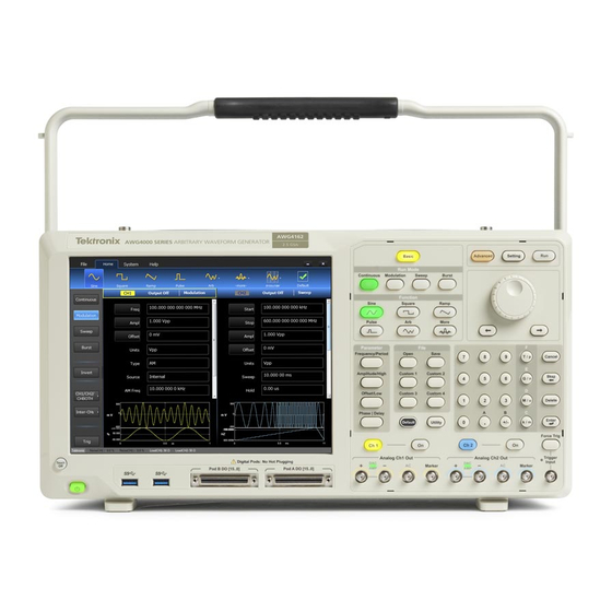
Tektronix AWG4162 Technical Reference (66 pages)
Arbitrary Waveform Generator
Brand:
Tektronix
| Category:
Laboratory Equipment
| Size: 0 MB
Table of Contents
Table of Contents
5
Important Safety Information
9
General Safety Summary
9
Service Safety Summary
11
Terms in this Manual
12
Symbols and Terms on the Product
12
Service Safety Summary
13
Preface
15
Finding Other Information
15
Manual Conventions
15
Specifications
17
Electrical Specifications
17
Table 1: Clock Generator
17
Table 2: Skew Control (Analog to Analog Skew)
18
Table 3: Skew Control (Analog to Digital Skew)
18
Table 4: Skew Control (Analog to Trigger/Marker Skew)
18
Table 5: Operating Mode for Basic, Nominal
18
Table 6: Waveforms (Basic Mode), Nominal
19
Table 7: Analog Output (Basic Mode), Frequency/Period
20
Table 8: Analog Output (Basic Mode), Amplitude
21
Table 9: Analog Output (Basic Mode), Vocm
21
Table 10: Analog Output (Basic Mode), Offset
22
Table 11: Analog Output (Basic Mode), Window
22
Table 12: Analog Output (Basic Mode), Sine Wave
23
Table 13: Analog Output (Basic Mode), Square Wave
23
Table 14: Analog Output (Basic Mode), Pulse
23
Table 15: Ramp
24
Table 16: Arbitrary
24
Table 17: DC
24
Table 18: Basic Mode Modulation
24
Table 19: Sweep
25
Table 20: Advanced Channel Functionality
25
Table 21: Operating Mode for Advanced, Nominal
25
Table 22: Advanced Run Mode
26
Table 23: Waveforms (Advanced Mode), Nominal
26
Table 24: Analog Output of Advanced Mode (Amp/Direct DAC/AC)
27
Table 25: Auxiliary Ports: Marker Output
31
Table 26: Auxiliary Ports: Trigger/Gate Input
32
Table 27: Auxiliary Ports: Digital Output (with Option)
32
Table 28: Auxiliary Ports: Memory Depth (Digital Output (with Option))
32
Table 29: Auxiliary Ports: Sync In/Out
33
Table 30: Auxiliary Ports: Reference Clock Input
33
Table 31: Auxiliary Ports: 10 Mhz Reference Clock Output
33
Table 32: Auxiliary Ports: External Sampling Clock Input
33
General Specifications
34
Table 33: Auxiliary Ports: External Modulation Input
34
Table 34: Power
34
Table 35: Environmental
34
Table 36: Physical Characteristics
34
Prerequisites
37
Self Tests
38
Error Codes
39
Table 37: INIT and SYNCH Error Codes
39
Table 38: Diagnostic Error Codes
42
Required Equipment
44
Basic Mode: Frequency/Period Test
45
Figure 1: Frequency/Period Test
45
Amplitude Test
46
Figure 2: 50 Ω Terminator Accuracy
46
Figure 3: Amplitude Test, Basic Mode
46
Figure 4: Amplitude Test, Advanced Mode
47
DC Offset and Vocm Tests
48
Figure 5: 50 Ω Terminator Accuracy
48
Figure 6: DC Offset/Vocm Tests, Basic Mode
49
Figure 7: DC Offset/Vocm Test, Advanced Mode
50
Basic Mode: AC Flatness Test
51
Figure 8: 50 Ω Terminator Accuracy
51
Figure 9: 1 Khz Setup for AC Flatness Test
51
Figure 10: >1 Khz Setup for AC Flatness Test
52
Basic Mode: Harmonics Distortion Test
53
Figure 11: Harmonic Distortion Tests
53
Basic Mode: Spurious Test
54
Figure 12: Spurious Tests
54
Test Record
55
Advertisement
Advertisement
Related Products
Tektronix A6902B
Tektronix AWG410
Tektronix AWG420
Tektronix AWG430
Tektronix AWG70001A
Tektronix AWG7000B Series
Tektronix AWG7 1B Series
Tektronix AWG2020
Tektronix AWG50BUP Option S39
Tektronix AWG7051
Tektronix Categories
Test Equipment
Measuring Instruments
Amplifier
Portable Generator
Printer
More Tektronix Manuals
Login
Sign In
OR
Sign in with Facebook
Sign in with Google
Upload manual
Upload from disk
Upload from URL